SNAU294 May   2024 LMX1205


  1.   1
  2.   Description
  3.   Features
  4.   Applications
  5.   5
  6. 1Evaluation Module Overview
    1. 1.1 Introduction
    2. 1.2 Kit Contents
    3. 1.3 Specification
    4. 1.4 Device Information
  7. 2Hardware
    1. 2.1 Jumper Information
    2. 2.2 Setup
      1. 2.2.1 Evaluation Setup Requirement
      2. 2.2.2 Connection Diagram
    3. 2.3 Power Requirements
    4. 2.4 Reference Clock
    5. 2.5 Output Connections
    6. 2.6 Test Points
  8. 3Software
    1. 3.1 Software Description
    2. 3.2 Software Installation
    3. 3.3 USB2ANY Interface
  9. 4Implementation Results
    1. 4.1 Buffer Mode
    2. 4.2 Divider Mode
    3. 4.3 Multiplier Mode
    4. 4.4 SYSREF Generation
  10. 5Hardware Design Files
    1. 5.1 Schematics
    2. 5.2 PCB Layouts
    3. 5.3 Bill of Materials (BOM)
  11. 6Additional Information
    1. 6.1 Trademarks

Jumper Information

Jumper J28, J29 and J30 determines the supply voltage to the board.

  • When using the onboard LDOs, set these jumpers to the "LDO" position. This is the default EVM configuration.
  • To bypass the LDOs, set these jumpers to the "VCCIN" position.
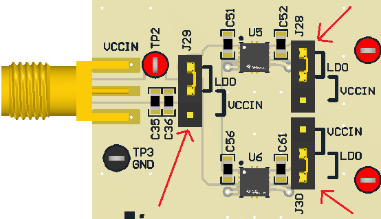
LMX1205EVM Jumper Configuration Figure 2-1 Jumper Configuration