SNAU310 June 2024 LMKDB1102 , LMKDB1202
5.1 Schematics
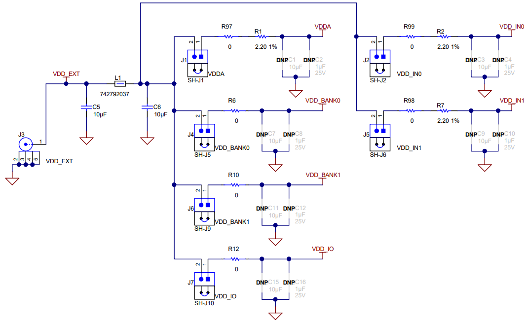 Figure 5-1 Power Supply
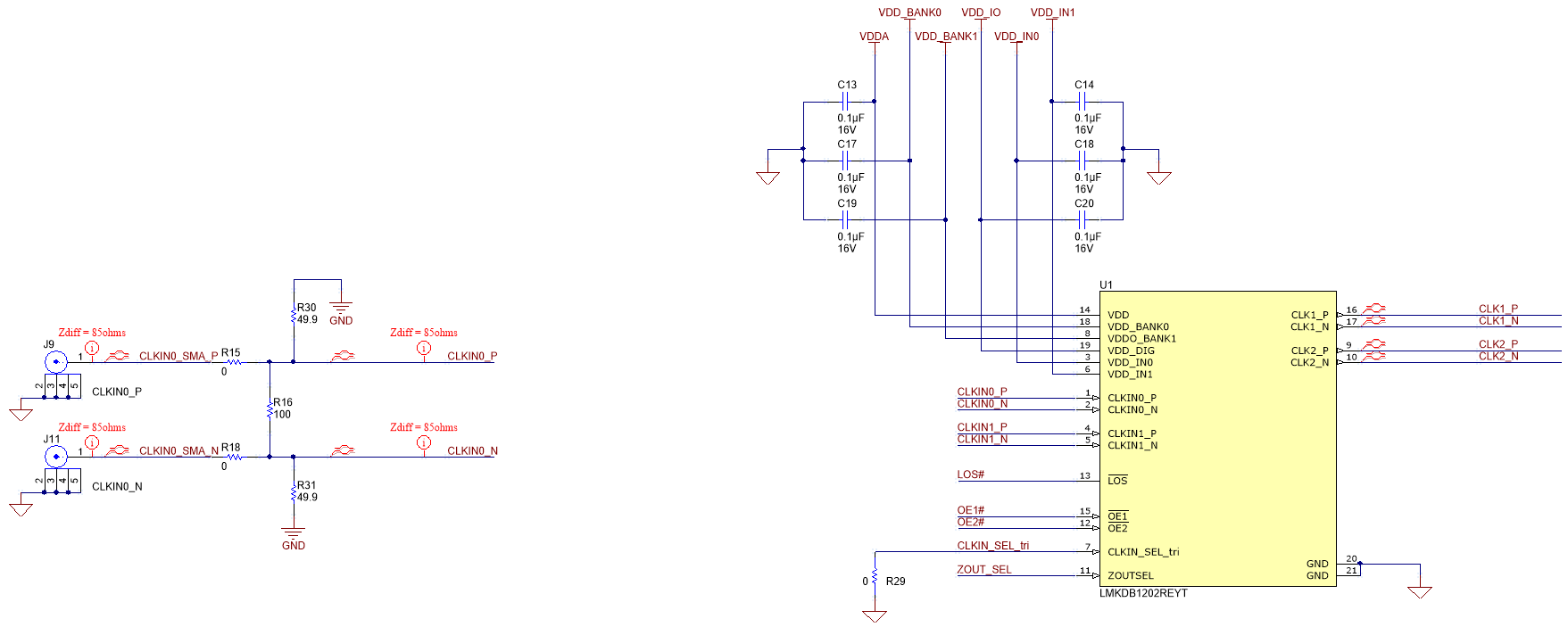 Figure 5-2 LMKDB1102 Device and CLKIN0_P/N
Reference
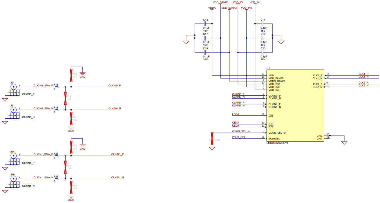 Figure 5-3 LMKDB1202 Device and CLKIN#_P/N Reference
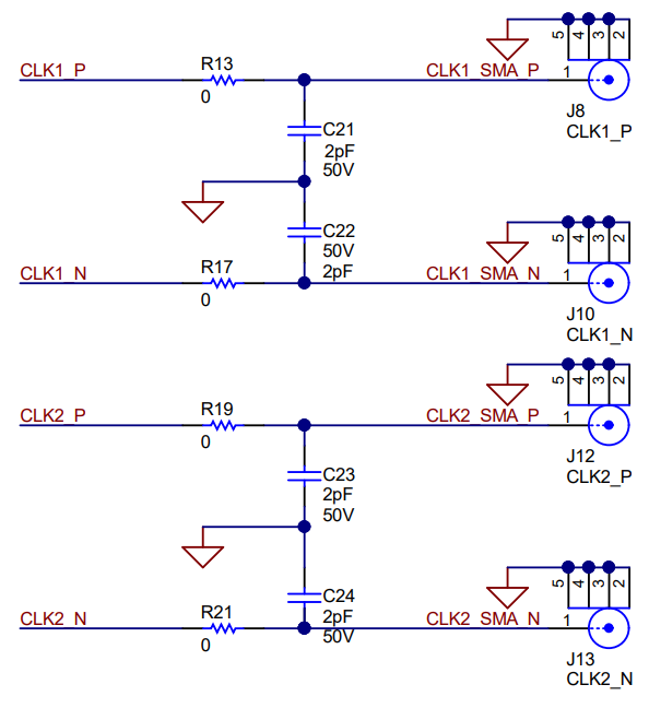 Figure 5-4 Clock Outputs CLK1 and CLK2
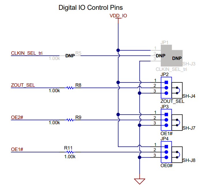 Figure 5-5 Output Enable Pins (OE#) and LMKDB1102
Logic I/O Jumpers
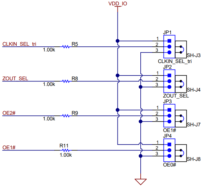 Figure 5-6 Output Enable Pins (OE#) and LMKDB1202
Logic I/O Jumpers
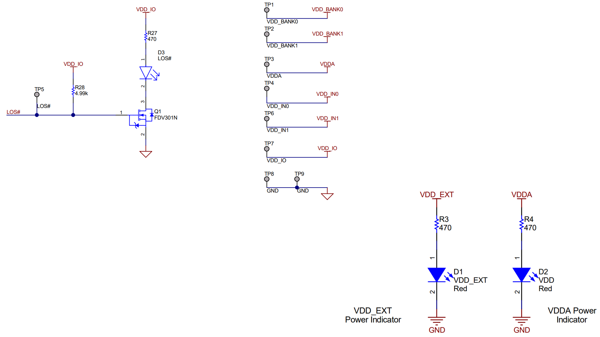 Figure 5-7 Status LEDs and Test Points