SNIA053 june 2023 TMP61-Q1
3 Test Implementation
A DC power of 15 V is applied to the signal conditioning board.
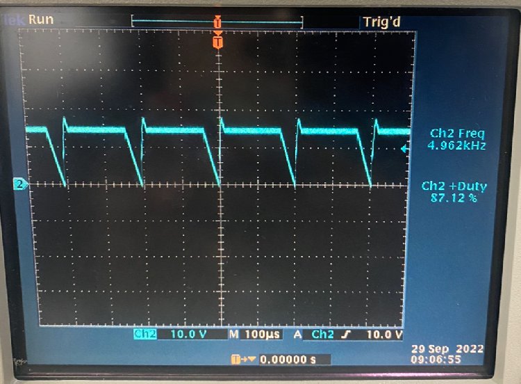
An analog PWM signal set to an 80% duty cycle at 15 kHz is applied to the IN+ pin of the UCC21732-Q1. The input waveform is shown in Figure 3-1. The isolated gate driver boosts the input to a 15-V output on OUTA to drive the IGBT Module MOSFETs through pin 13.
 Figure 3-1 Input PWM
Signal
 Figure 3-2 Output PWM
Driver Signal
Figure 3-2 Output PWM
Driver SignalThe analog inputs from the thermistors are measured to confirm that the correct temperature is reported. The software on the MSP430 converts the analog voltage to a temperature value for both the TMP6 and NTC ring lug thermistors. The temperature is output to the serial monitor, as shown in Figure 3-3.
 Figure 3-3 Thermistor
Serial Data
Figure 3-3 Thermistor
Serial DataAfter the initial measurements are confirmed, power is applied to the IGBT module. The IGBT module receives 15 V DC and 20 A.

Figure 3-4 Load and DC Supplies
The oscilloscope measures the switching of the IGBT module and the temperature of the system, particularly the heat sink, which is monitored to make sure changes are occurring. The heat sink temperature steadily increases, increasing the temperature measurements from the ring lug thermistors.
 Figure 3-5 IGBT Module
Output
 Figure 3-6 Heat Sink
Temperature
Figure 3-6 Heat Sink
TemperatureThe system is allowed to run and the heat sink temperature is monitored as the system begins to rise in temperature. Signal measurements are taken from both ring lug thermistors as well as thermal images of the ring lugs and heat sink.