SNLA356 September 2020 DS90UB941AS-Q1 , DS90UH941AS-Q1
2.4.2 Non-Burst Mode With Sync Events
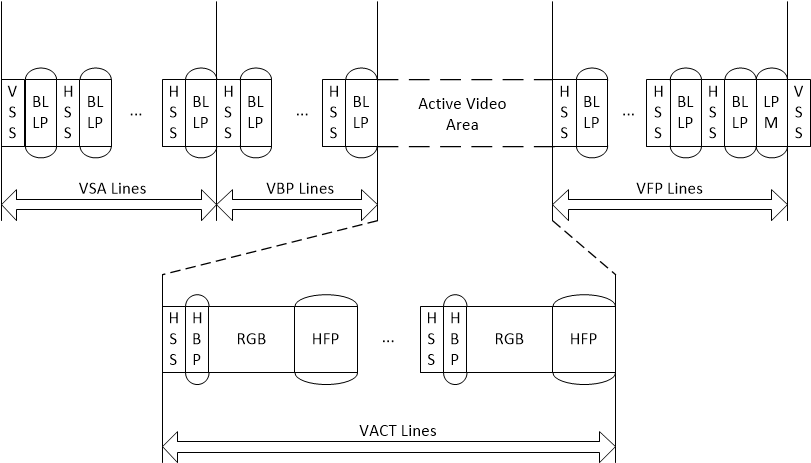
- The DSI transmitter must convey accurate DPI-type timing for HSS, and VSS packets as well as the pixel transmission rate for each active line to match the desired video timing.
- Since Event Mode does not utilize HSE and VSE packets to define the falling edge of the HSYNC/VSYNC signals, the serializer must be programmed to generate the desired sync widths with the DSI_HSW_CFG and DSI_VSW_CFG registers.
- The timing of the rising edge of each sync signal is defined by the received timing of the HSS/VSS DSI short packets (which also defines the horizontal and vertical back porch value for the video).
- The output pixel rate can be defined by the DSI clock rate in continuous clock mode or by the REFCLK source applied to the DS90UB941AS-Q1.
 Figure 2-2 Non-Burst Mode with Sync Events
Packet Structure.