SNLA446 November 2024 DS320PR410
3 Low Level Page
The following section describes features of the Low Level Page in DS320PR410 GUI. This page can be used to access individual registers of each DS320PR410 device, change specific device settings, verify current device status, and to verify changes from the GUI High Level Page. For further information on DS320PR410 registers, please refer to the DS320PR410 Programming Guide.
- Use the Device Select drop-down menu shown
in Figure 3-1 to select which device is desired to read or write to. The
DS320PR410-RSC-EVM includes four downstream and four upstream devices.
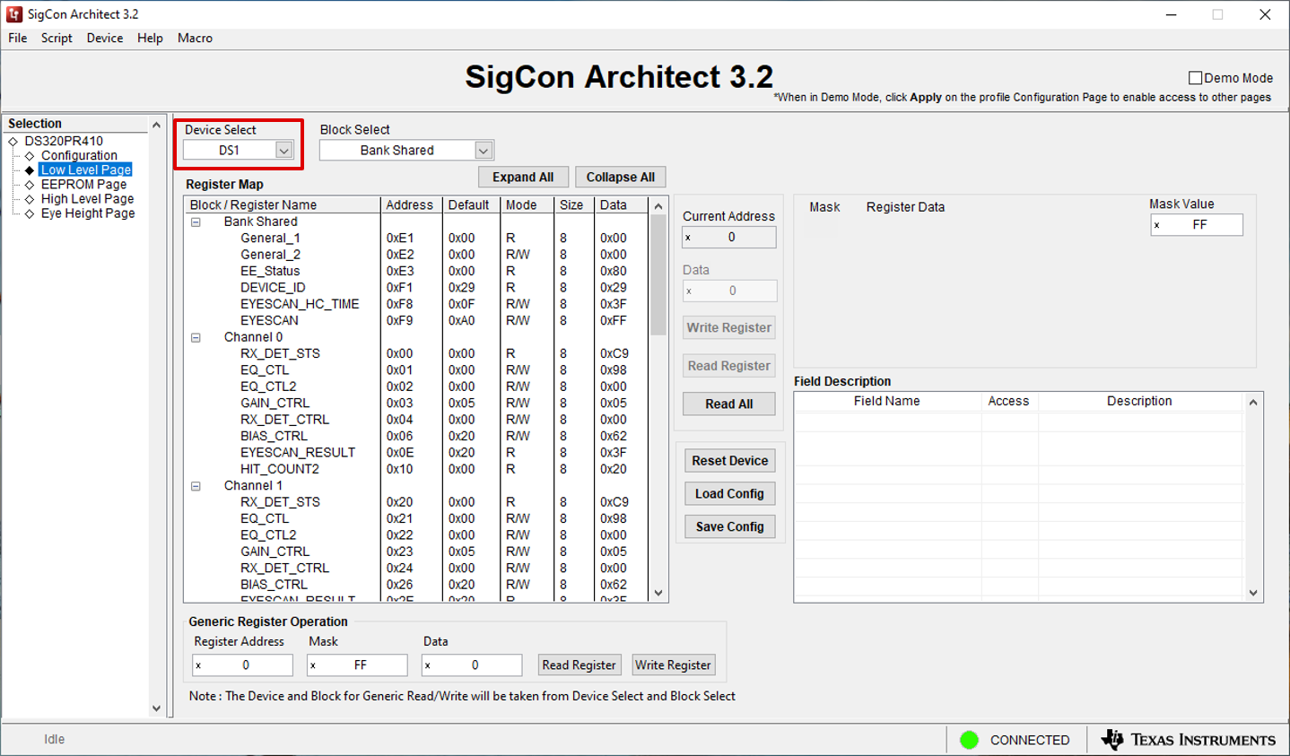
Figure 3-1 Low Level Page: Device Select Drop-Down - Once the desired device is selected using the
Device Select drop-down, the complete register map appears in the GUI
Register Map table. Use the Block Select drop-down menu shown
in Figure 3-2 to jump to the desired section of the table to view device
Bank Shared registers, device Channel registers, and device
Bank registers. The register Bank includes all device channels
0-3.
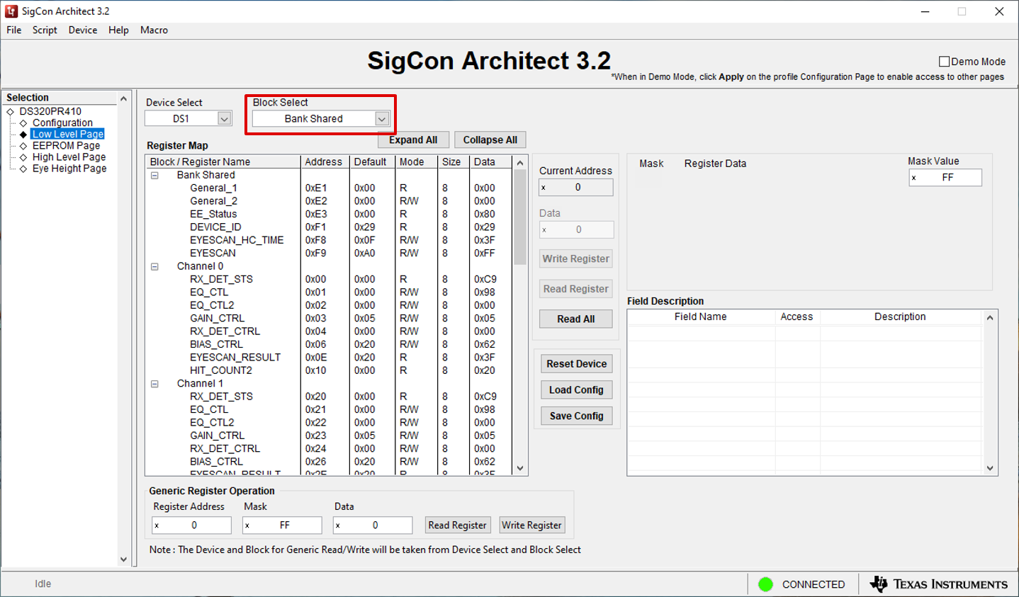
Figure 3-2 Low Level Page: Block Select Drop-Down Menu - Click the Real All button to read the
configuration registers of the entire device into the GUI. Alternately, click a
specific register, and click the Read Register device to update the
selected target register in the GUI. The Current Address field
automatically updates with the selected (highlighted) register. This field and
associated buttons are shown in Figure 3-3.
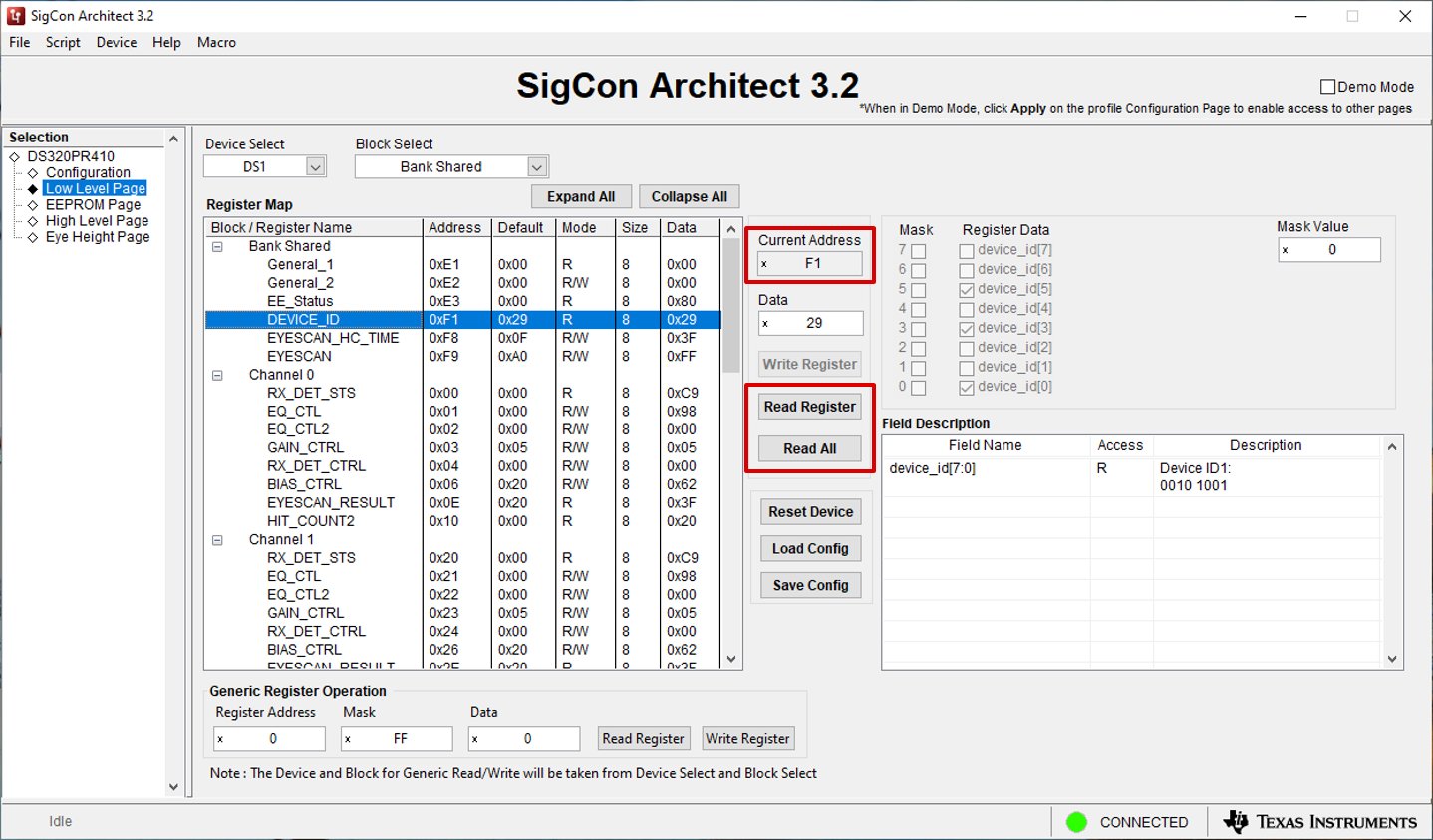
Figure 3-3 Low Level Page: Read Register Buttons - To write to the selected register, select or
deselect the boxes in the Register Data fields or manually enter a hex
value into the Data field. Then, click the Write Register button
to write the specified data into the highlighted device register. To verify the
change was made, click the Read Register button. Note the Field
Description table describes the function of each bit in the highlighted
register. This field and associated buttons or check buttons are highlighted in
Figure 3-4.
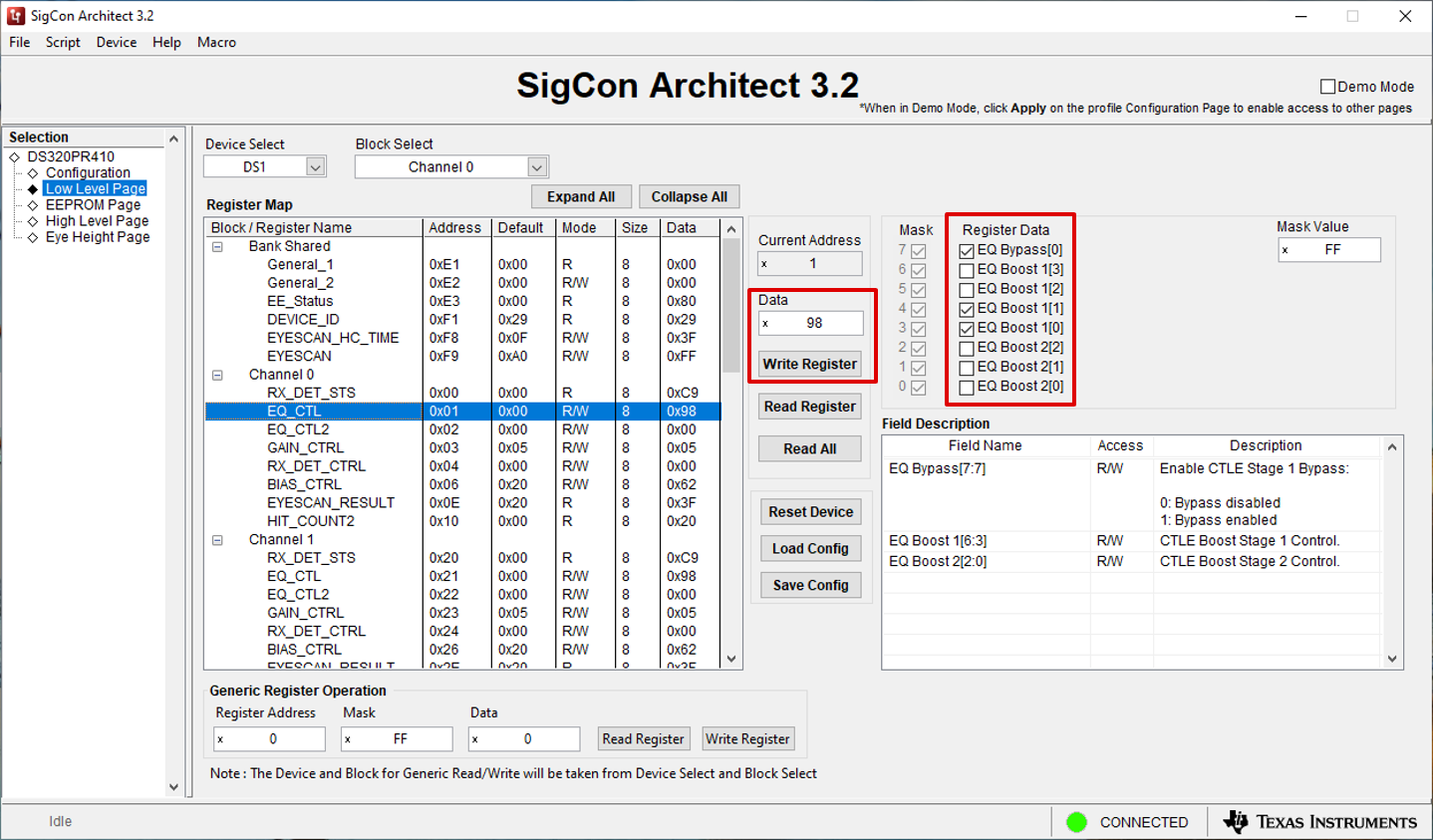
Figure 3-4 Low Level Page: Data Field and Write Register Button - Use the Save
Config button to save the current register configuration in a .cfg file
and the Load Config button to load a device .cfg file. Click the Reset
Device button to reset every device register to the Default
register value specified in the Register Map. Each of these buttons are
outlined in Figure 3-5.
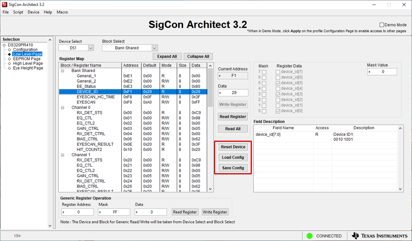
Figure 3-5 Low Level Page: Reset, Load, and Save Device Configuration Buttons - If desired, the Generic
Register Operation portion of the page can be used to read and write
generic device registers with a custom mask. This can be found at the bottom of
the Low Level Page, as indicated by Figure 3-6.
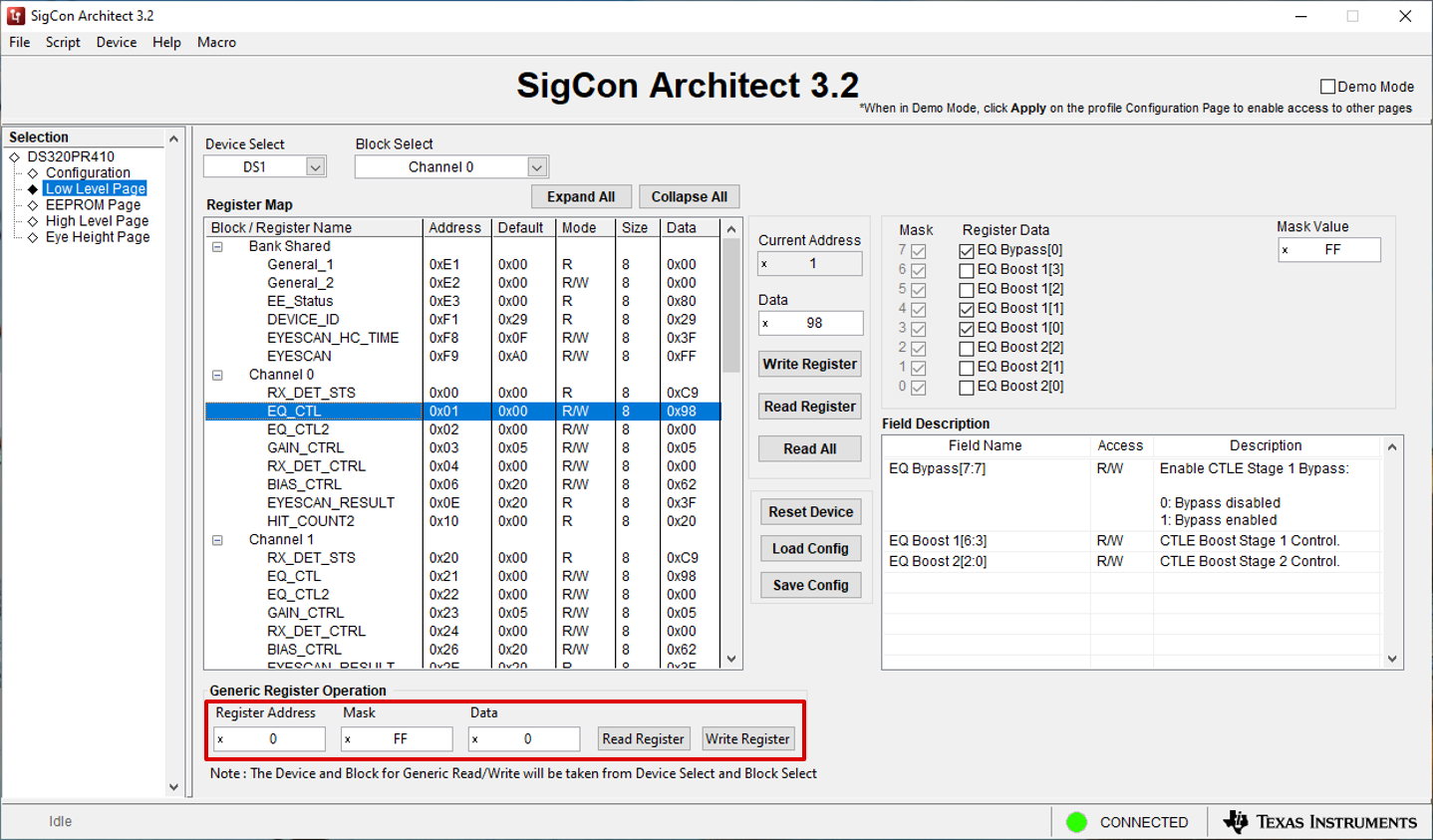
Figure 3-6 Low Level Page: Generic Register Operation