SNLA474A October 2024 – October 2024 DS90UB971-Q1
3.3 MODE Selection
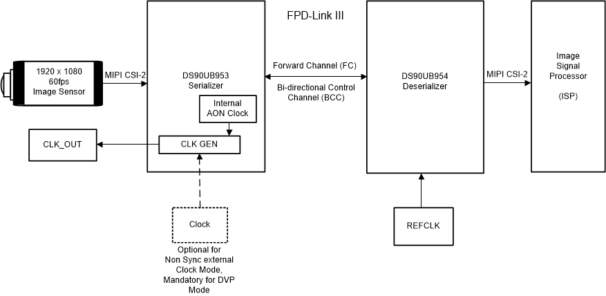
FPD-Link III and IV CSI-2 ADAS serializer support multiple operational modes including synchronous mode and non-synchronous mode. In synchronous mode, the serializer utilizes the back channel signal from the deserializer as a clock reference to generate the forward channel signal, as well as an optional clock output signal (CLKOUT) to a sensor. Due to the architecture of synchronous mode, transient disruption to the back channel signal between the deserializer and the serializer can cause the serializer to temporarily lose the clock reference. When this occurs, there can be a corresponding disruption of the forward channel signal to the deserializer. Conversely, when using non-synchronous mode there is no relationship between the forward channel signal and the back channel signal. Errors in the back channel signal do not impact the serializer ability to transmit a valid forward channel signal which contains the mission critical video data.
 Figure 3-3 FPD-Link ADAS Clocking Architecture
There are two different non-synchronous modes available across FPD-Link III/IV ADAS serializer devices:
- Non-synchronous mode with external CLKIN
- Available on DS90UB953-Q1, DS90UB935-Q1, DS90UB635-Q1, and DS90UB971-Q1 at all supported rates
- CLKOUT feature is available
- Non-synchronous mode with internal AON clock
- Available on DS90UB953-Q1, DS90UB935-Q1, and DS90UB635-Q1
- Available on DS90UB971-Q1 only in FPD-Link III mode (4Gbps)
- CLKOUT feature is disabled
TI recommends provisioning camera module designs to support either mode in hardware so that there is flexibility to evaluate both modes during ESD qualification testing. Many system designers prefer synchronous mode to reduce component counts, to enable higher speed back channel GPIO, and to allow for spread spectrum clocking. Depending on the system needs for data rate and CLKOUT capability, the system designer can also provision to add an external oscillator input to the serializer to use non-synchronous external CLKIN mode as an option. From there, the system performance can be evaluated in multiple modes during ESD qualification testing. If the system preference is to utilize synchronous mode and the ESD performance meets the system designer's needs in that mode, then the oscillator can be removed from the BOM population in the final build.