SNLU254A November 2020 – July 2022 DS160PT801
3.7 Diagnostic Page
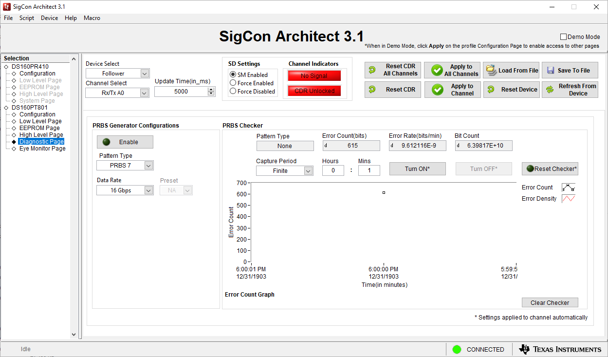
 Figure 3-10 Diagnostic Page Screenshot
The Diagnostic page contains features of the retimer that are meant to be used for evaluating the signal integrity of a system. By using the PRBS Checker and PRBS Generator functions of the retimer, it is possible to determine the Bit Error Ratio (BER) of a channel. This operational mode of the retimer does not operate through the PCIe protocol. It forced the retimer to simply transmit an electrical pattern specified by a user. There is also an option to force the transmission of a specific PCIe compliance pattern. The fields available in this page are as follows:
- Enable Button enables or disables the PRBS or compliance pattern generator with the specified pattern type and datarate. If using a PCIe compliance pattern, it is possible to also force a specific PCIe preset value for the transmitted signal.
- Pattern Type Dropdown modifies the pattern that is transmitted by the retimer.
- Data Rate Dropdown changes the datarate of the signal transmitted.
- Preset Dropdown will change the PCIe of the output signal when a compliance pattern is selected in the pattern type dropdown.
- Capture Period Dropdown modifies the time period used to capture and count errors using the PRBS Checker.
- Turn ON* Button turns on the PRBS checker.
- Turn OFF* Button turns off the PRBS checker.
- Reset Checker* resets the error count for the PRBS checker.
- Error Count Graph displays the amount of errors accumulated by the PRBS checker over time.
- Clear Checker Button clears the error count graph.