SNLU291B March 2021 – August 2022 MCT8316Z
2 Introduction
The MCT8316Z is a 4.5-V to 35-V, 8-A peak integrated three-phase gate driver IC with sensored trapezoidal control for motor drive applications. It provides three integrated half-bridges and a sensored trapezoidal algorithm capable of directly driving a 3-phase brushless-DC motor. The hardware interface variant (MCT8316ZT) integrates an adjustable buck regulator, protection features, and flexible parameter settings such as slew rate control and buck output voltage. See Table 3-1.
Device Name | Variant |
|---|---|
MCT8316Z0T | Buck regulator and Hardware |
MCT8316Z0R | Buck regulator and SPI |
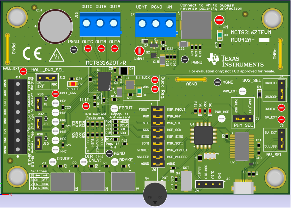
The MCT8316ZTEVM includes an onboard FTDI chip to convert USB communication from the micro-USB connector into UART. An onboard MSP430FR2355 MCU translates the UART communication and onboard potentiometer into control signals and a variable duty cycle for the PWM input of the MCT8316Z. It can also provide SPI communication for the SPI variant of the MCT8316Z device. There are many user-selectable jumpers, resistors, connectors, and test points to evaluate the features of the device and configure device-specific settings.
This document serves as a startup guide to supplement the MCT8316ZTEVM. It is intended for engineers to design, implement, and validate reference hardware for the MCT8316ZT (H/W variant) along with the device data sheet.
 Figure 2-1 MCT8316ZTEVM Printed Circuit Board (PCB - Top View)