SNLU291B March 2021 – August 2022 MCT8316Z
4.3 MSP430FR2355 Microcontroller
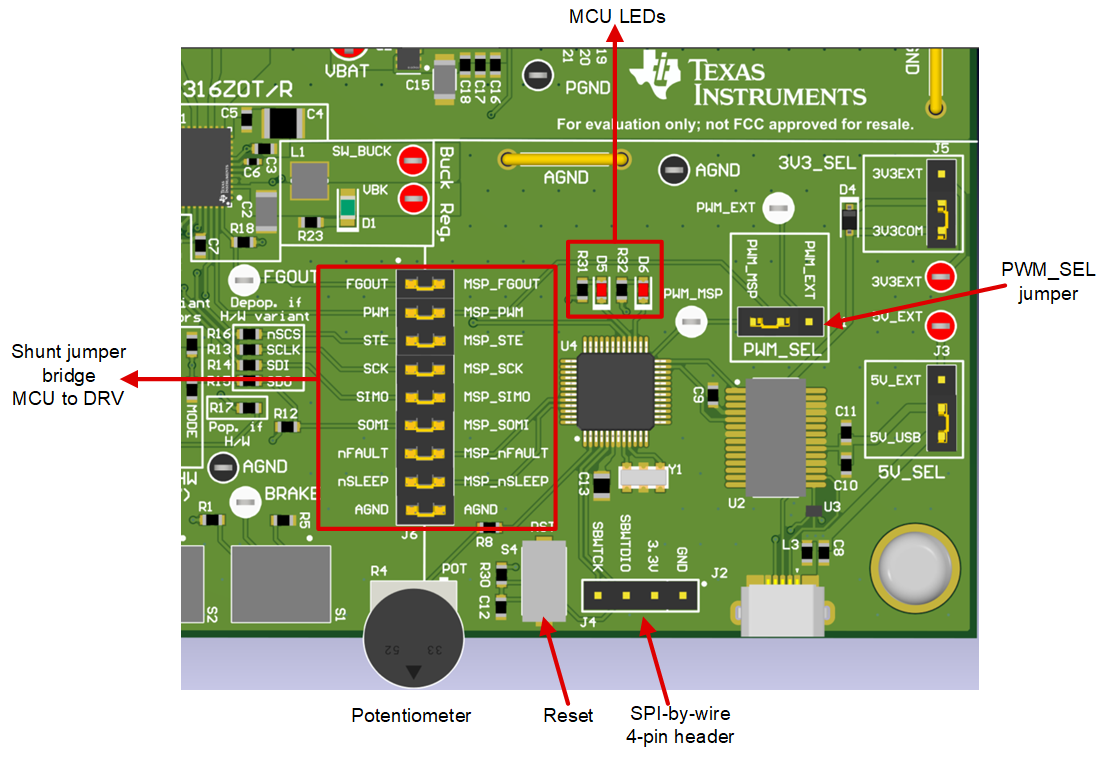
The MCT8316ZTEVM includes the MSP430FR2355 low-power MCU (as shown in Figure 4-4) to provide the pulse-width modulation (PWM) signal required to commutate the motor. The MCU outputs a 20-kHz PWM signal (PWM_MSP), and the duty cycle (ranging from 0–100%) is controlled by the potentiometer R4. The motor speed will increase the more the potentiometer is turned counterclockwise, and will decrease when turned clockwise. To select whether the PWM signal from the MSP or an external PWM is sourced to the MCT8316Z, use the PWM_SEL jumper J1.
To program the MSP430FR2355, an external MSP430 LaunchPad™ must be connected to the four-pin connector J4. Many MSP430 LaunchPads provide an onboard eZ-FET Debug Probe to flash the program into the microcontroller and support debug using a 2-pin Spy-by-Wire (SBW).
The user can use the Reset (RST) button at any time to restart the MCU program. Two active-low LEDs, D5 and D6, can be used for debug purposes as well.
Finally, a shunt jumper bridge on 18-pin connector J6 ties all signals between the microcontroller and the MCT8316Z device. These jumpers can be inserted or removed as needed to isolate the microcontroller from the gate driver. This allows for microcontroller signal debugging or using the MCT8316ZTEVM as a standalone gate driver with an external microcontroller.
 Figure 4-4 MSP430FR2355 MCU on MCT8316ZTEVM