SNLU341A December 2023 – July 2024 MCT8314Z
2.7.2 SPI Variant Resistor Settings
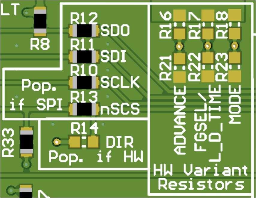
The MCT8314ZS replaces the MODE, ADVANCE, and FGOUT/LOCK_DET_TIME pins with SPI pins (SDI, SDO, SCLK, nSCS) to configure control registers and read status registers. When using the MCT8314ZS:
- SPI enable resistors in the Pop. if SPI silk screen box needs be populated (R10-R13).
- The resistor in the Pop. if HW silkscreen box (R17) needs be depopulated.
- Resistor dividers in the Hardware Variant Resistors silk screen box needs be depopulated (R16-R18, R21-R23).
An example of this setup is shown in Figure 3-8.
 Figure 2-8 Resistors for MCT8314ZS (SPI
variant)
Figure 2-8 Resistors for MCT8314ZS (SPI
variant)Table 3-4 shows the recommended resistor values to when using a MCT8314ZS. The default resistor configurations are in bold.
Table 2-4 Recommended SPI Resistor Values for MCT8314ZS
| Setting | Name | Description | Resistor | Configuration |
|---|---|---|---|---|
| SDO | Serial Data Out | Serial out of the MCT8314Z | R15 | R15 = 0Ω |
| SDI | Serial Data In | Serial input of the MCT8314Z | R14 | R14 = 0Ω |
| SCLK | Serial Clock | Clock generated by the MCU | R13 | R13 = 0Ω |
| nSCS | Chip Select | Pulled low by the MCU to enable communication | R16 | R16 = 0Ω |
Table 3-5 show the status of populated and DNP resistors for the MCT834Z variants.
Table 2-5 Status of Resistors for MCT8314Z Variants
| Device | R13-R16 status | R17 status | R16-R18 and R21-R23 status |
|---|---|---|---|
| MCT8314ZH | DNP | Populated | User adjustable |
| MCT8314ZS | Populated | DNP | DNP |