SNLU341A December 2023 – July 2024 MCT8314Z
2.7.1 Hardware Variant Settings
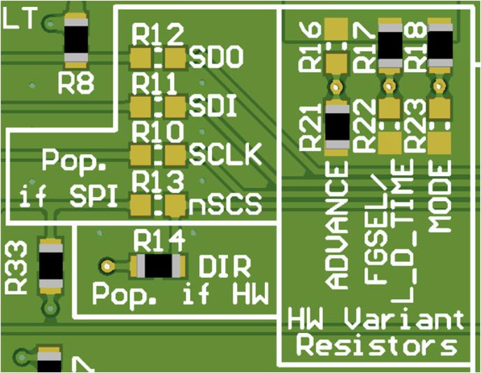
The MCT8314ZH devices uses configurable resistor dividers to control the MODE, ADVANCE, FGOUT, and LOCK_DET_TIME settings. When using the MCT8314ZH:
- SPI enable resistors in the Pop. if SPI silk screen box needs to be depopulated (R10–R13).
- DIR resistor R14 in the Pop. if HW silk screen box needs be populated with a 0Ω resistor.
- The resistor dividers in the HW Variant Resistors silk screen box needs be populated according to the desired settings (R16–R18 and R21–R23).
An example of this setup is shown in Figure 3-7.
 Figure 2-7 Resistor Divider Settings for
MCT8314ZH (Hardware Variant)
Figure 2-7 Resistor Divider Settings for
MCT8314ZH (Hardware Variant)Table 3-4 shows the user-adjustable resistor divider settings when using the MCT8314ZH. R16–R18 resistors connect to AVDD and R21–R23 resistors connect to AGND. The default resistor divider configurations are in bold.
Table 2-3 User-Adjustable Resistor Divider Settings for MCT8314ZH Variant
| Setting | Name | Description | Resistors (AVDD and AGND) | Configuration | Setting |
|---|---|---|---|---|---|
| MODE | PWM Control Mode | Selects the Hall configuration, modulation, Asynchronous Rectification (ASR), and Automatic Asynchronous Rectification (AAR) settings | R18 and R23 | R23 = 0Ω | Analog Hall Input, Asynchronous modulation, ASR and AAR Disabled . |
| R23 = 22kΩ | Digital Hall Input, Asynchronous modulation, ASR and AAR Disabled. | ||||
| R23 = 100kΩ | Analog Hall Input, Synchronous modulation, ASR and AAR Disabled. | ||||
| R18 = R23 = DNP | Digital Hall Input, Synchronous modulation, ASR and AAR Disabled. | ||||
| R18 = 100kΩ | Analog Hall Input, Synchronous modulation, ASR and AAR Enabled. | ||||
| R18 = 22kΩ | Digital Hall Input, Synchronous modulation, ASR and AAR Enabled. | ||||
| R18 = 0Ω | Digital Hall Input, Asynchronous modulation, ASR and AAR Enabled. | ||||
| FGOUT/L_D_TIME | FGOUT and Motor lock configuration | Sets the FG output commutation frequency multiplier and time required to detect a motor lock fault condition | R17 and R22 | R22 = 0Ω | Motor Lock Detection time = 100ms and FGOUT = 3x commutation frequency. |
| R22 = 22kΩ | Motor Lock Detection time = 500ms and FGOUT = 3x commutation frequency. | ||||
| R22 = 100kΩ | Motor Lock Detection time = 1000ms and FGOUT = 3x commutation frequency. | ||||
| R17 = R22 = DNP | Motor Lock Detection time = 5000ms and FGOUT = 3x commutation frequency. | ||||
| R17 = 100kΩ | Motor Lock Detection time = 300ms and FGOUT = 1x commutation frequency. | ||||
| R17 = 22kΩ | Motor Lock Detection time = 500ms and FGOUT = 1x commutation frequency. | ||||
| R17 = 0Ω | Motor Lock Detection time = 1000ms and FGOUT = 1x commutation frequency. | ||||
| ADVANCE | Advance | Advances the lead angle by a selectable value (in electrical degrees) | R16 and R21 | R21 = 0Ω | 0° |
| R21 = 22kΩ | 4° | ||||
| R21 = 100kΩ | 11° | ||||
| R16 = R21 = DNP | 15° | ||||
| R16 = 100kΩ | 20° | ||||
| R16 = 22kΩ | 25° | ||||
| R16 = 0Ω | 30° |