SNLU342 December 2023 MCT8315Z
2.7.1 Hardware Variant Resistor Settings
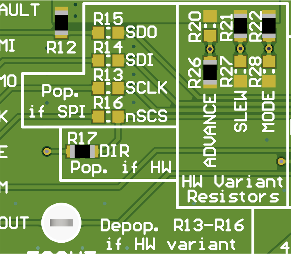
The MCT8315ZH and MCT8315ZT devices uses configurable resistor dividers to control the MODE, SLEW, and ADVANCE settings. When using the MCT8315ZH or MCT8315ZT:
- SPI enable resistors in the Pop. if SPI silkscreen box needs to be depopulated (R13–R16).
- DIR resistor R17 in the Pop. if HW silkscreen box needs to be populated.
- The resistor dividers in the HW Variant Resistors silkscreen box needs to be populated according to the desired settings (R20–R22 and R26–R28).
This setup is shown in Figure 3-7.
 Figure 2-7 Resistor Divider Settings for MCT8315ZH or MCT8315ZT (Hardware Variants)
Table 3-4 shows the user-adjustable resistor divider settings when using the MCT8315ZH or MCT8315ZT. R20–R22 resistors connect to AVDD and R26–R28 resistors connect to AGND. The default resistor divider configurations are in bold.
Table 2-3 User-Adjustable Resistor Divider Settings for MCT8315ZH or MCT8315ZT (Defaults in Bold)
| Setting | Name | Description | Resistors (AVDD and AGND) | Configuration | Setting |
|---|---|---|---|---|---|
| MODE | PWM Control Mode | Selects the Hall configuration, modulation, Asynchronous Rectification (ASR), and Automatic Asynchronous Rectification (AAR) settings | R22 and R28 | R28 = 0 Ω | Analog Hall Input, Asynchronous modulation, ASR and AAR Disabled |
| R28 = 22 kΩ | Digital Hall Input, Asynchronous modulation, ASR and AAR Disabled | ||||
| R28 = 100 kΩ | Analog Hall Input, Synchronous modulation, ASR and AAR Disabled | ||||
| R22 = R28 = DNP | Digital Hall Input, Synchronous modulation, ASR and AAR Disabled | ||||
| R22 = 100 kΩ | Analog Hall Input, Synchronous modulation, ASR and AAR Enabled | ||||
| R22 = 22 kΩ | Digital Hall Input, Synchronous modulation, ASR and AAR Enabled | ||||
| R22 = 0 Ω | Digital Hall Input, Asynchronous modulation, ASR and AAR Enabled | ||||
| SLEW | Slew Rate | Phase pin slew rate switching low to high (10-90%) and high to low (90-10%) | R21 and R27 | R27 = 0 Ω | 25 V/μs |
| R21 = R27 = DNP | 50 V/μs | ||||
| R21 = 47 kΩ | 125 V/μs | ||||
| R21 = 0 Ω | 200 V/μs | ||||
| ADVANCE | Advance | Advances the lead angle by a selectable value (in electrical degrees) | R20 and R26 | R26 = 0 Ω | 0° |
| R26 = 22 kΩ | 4° | ||||
| R26 = 100 kΩ | 11° | ||||
| R20 = R26 = DNP | 15° | ||||
| R20 = 100 kΩ | 20° | ||||
| R20 = 22 kΩ | 25° | ||||
| R20 = 0 Ω | 30° |