SNLU342 December 2023 MCT8315Z
2.7.2 SPI Variant Resistor Settings
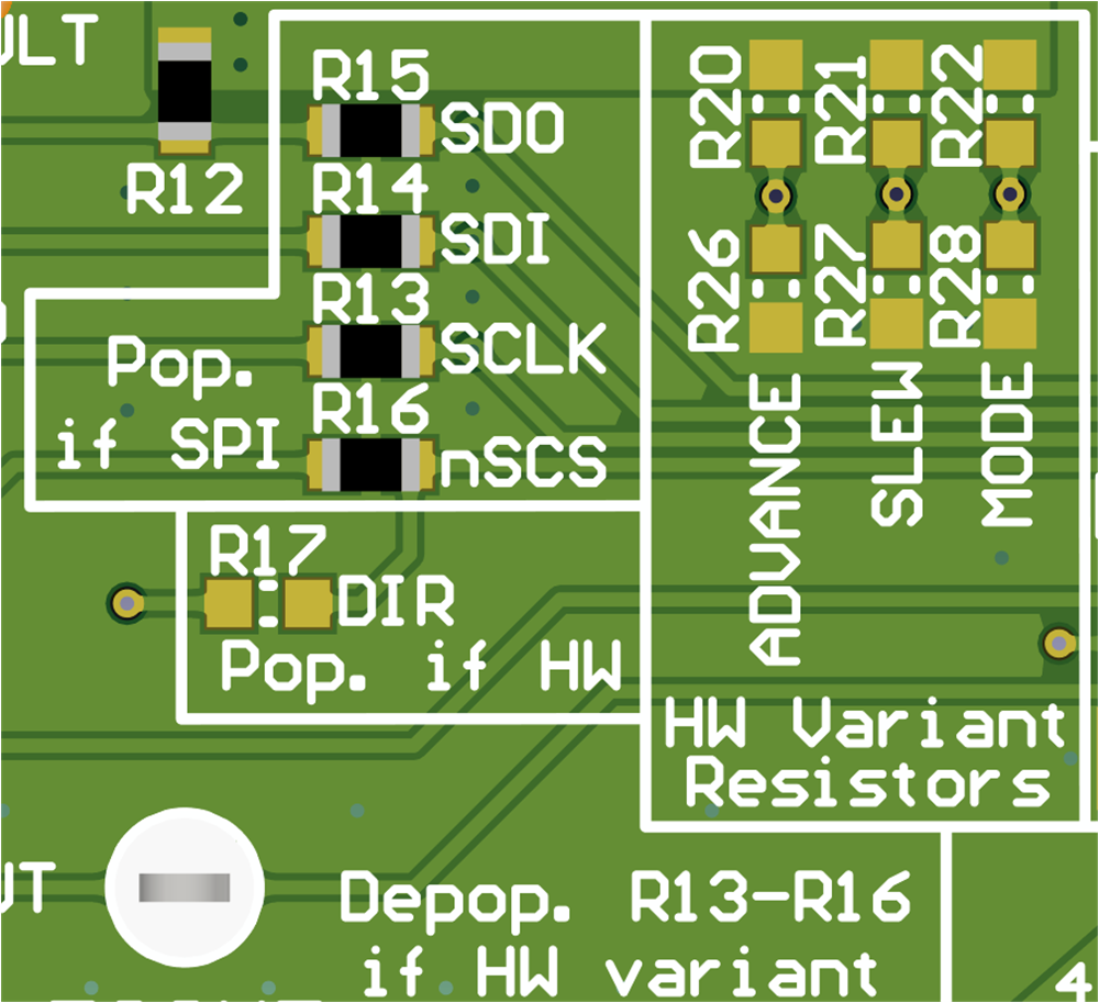
The MCT8315ZR replaces the MODE, ADVANCE, and SLEW pins with SPI pins (SDI, SDO, SCLK, nSCS) to configure control registers and read status registers. When using the MCT8315ZR:
- SPI enable resistors in the Pop. if SPI silkscreen box needs to be populated (R13-R16)
- The resistor in the Pop. if HW silkscreen box (R17) needs to be depopulated
- Resistor dividers in the Hardware Variant Resistors silkscreen box needs to be depopulated (R20-R22, R26-R28).
This setup is shown in Figure 3-8.
 Figure 2-8 Resistors for MCT8315ZR (SPI
variant)
Figure 2-8 Resistors for MCT8315ZR (SPI
variant)Table 3-4 shows the recommended resistor values to use when using a MCT8314ZR.
Table 2-4 Recommended SPI Resistor Values for
MCT8314ZR (Defaults in Bold)
| Setting | Name | Description | Resistor | Configuration |
|---|---|---|---|---|
| SDO | Serial Data Out | Serial out of the MCT8315Z | R15 | R15 = 0 Ω |
| SDI | Serial Data In | Serial input of the MCT8315Z | R14 | R14 = 0 Ω |
| SCLK | Serial Clock | Clock generated by the MCU | R13 | R13 = 0 Ω |
| nSCS | Chip Select | Pulled low by the MCU to enable communication | R16 | R16 = 0 Ω |
Table 3-5 show the status of populated and DNP resistors for the MCT8315Z variants.
Table 2-5 Status of Resistors for MCT8315Z
Variants
| Device | R13-R16 Status | R17 Status | HW Variant Resistors Status |
|---|---|---|---|
| MCT8315ZH or MCT8315ZT | DNP | Populated | User adjustable |
| MCT8315ZR | Populated | DNP | DNP |