SNLU342 December   2023 MCT8315Z


  1.   1
  2.   Description
  3.   Get Started
  4.   Features
  5.   Applications
  6.   6
  7. 1Evaluation Module Overview
    1. 1.1 Introduction
    2. 1.2 Kit Contents
    3. 1.3 Specification
    4. 1.4 Device Information
  8. 2Hardware
    1. 2.1 Quick Startup Guide
    2. 2.2 Hardware Setup
    3. 2.3 Hardware Connections Overview
    4. 2.4 Connection Details
    5. 2.5 MSP430FR2355 Microcontroller
    6. 2.6 LED Lights
    7. 2.7 User-Configurable Settings
      1. 2.7.1 Hardware Variant Resistor Settings
      2. 2.7.2 SPI Variant Resistor Settings
  9. 3Software
    1. 3.1 Firmware and GUI Application
    2. 3.2 MCT8315Z GUI
    3. 3.3 Running the GUI
    4. 3.4 Downloading Code Composer Studio and Importing GUI Firmware
    5. 3.5 Using the eZ-FET to Program the MSP430FR2355
  10. 4Hardware Design Files
    1. 4.1 Schematics
      1. 4.1.1 MCT8315Z 3-Phase Sensored Trapezoidal Motor Driver
      2. 4.1.2 Power Supplies
      3. 4.1.3 MCU Interface
      4. 4.1.4 User Interface
    2. 4.2 PCB Layouts
    3. 4.3 Bill of Materials (BOM)
  11. 5Additional Information
    1.     Trademarks

LED Lights

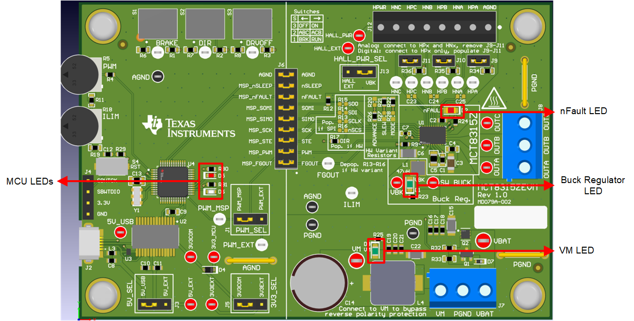
The MCT8315ZEVM has five status LEDs that provide the status of power supplies and functions of the evaluation module. By default, the VM LED and VBK LED lights up when the board is powered and the firmware has been flashed onto the microcontroller. Table 3-1 shows LED descriptions including those that are on during power up in bold and Figure 3-6 shows the locations of the LEDs.

Table 2-1 Description of MCT8315ZEVM LEDs (Default in Bold After Power Up)
Designator Name Color Description
D1 VBK Green Internal buck regulator is outputting
D2 nFAULT Red Lights up when fault condition has occurred on MCT8315Z
D3 VM Green Motor power is supplied to the board
D5 MSP_LED0 Red Used for UART or debugging
D6 MSP_LED1 Green Used for UART or debugging
GUID-20231201-SS0I-6JVC-CXLG-73ZVVXRVPV1N-low.png Figure 2-6 MCT8315ZEVM LEDs