SNOA475F October 2016 – September 2020 LMV791
- Trademarks
- 1Introduction
-
2What Parameters Should Be Tested?
- 2.1 Open-Loop Gain (AOL) and Phase Margin
- 2.2 Slew Rate
- 2.3 Common-Mode Rejection Ratio (CMRR) and Power Supply Rejection Ratio (PSRR)
- 2.4 Open-Loop Output Impedance (Zo)
- 2.5 Voltage Noise (en)
- 2.6 Current Noise (in)
- 2.7 Input Offset Voltage (VOS), Input Bias Current (Ib), and Quiescent Current (IQ)
- 2.8 Output Voltage Versus Output Current (Claw Curve)
- 2.9 Overload Recovery Time (tOR)
- 2.10 Common-mode Input Capacitance (CCM) and Common-mode Differential Capacitance (CDIFF)
- 2.11 Overshoot and Transient Response
- 2.12 Common-Mode Voltage Range (CMVR)
- 3Conclusion
- Revision History
2.6 Current Noise (in)
The second type of op amp noise is input current noise spectral density (in). Current noise is an input referred noise that gets converted to voltage by the input and feedback resistance of the circuit in accordance with Ohm's law. For large resistances, like ultra-low power devices, the contribution of current noise is significant. The op amp's current noise is usually given in units of femtoamps per square root hertz (fA/√Hz) or picoamps per square root hertz (pA/√Hz). Current noise is either characterized as a single value in the op amp's electrical characteristics table or as a curve over frequency. Similar to voltage noise, current noise over frequency may have both 1/f and broadband regions. To learn more about current noise (iin) please refer to the Texas Instruments Precision Labs video series on noise.
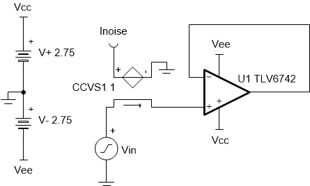
 Figure 2-18 Current Noise (in)
Test Circuit
Figure 2-18 Current Noise (in)
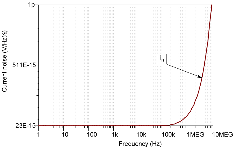
Test CircuitThe test circuit for current noise is very similar to the test circuit for voltage noise. This circuit adds in a current controlled voltage source (CCVS1) to convert current to voltage with a transresistance of 1V/A. The CCVS is added as a workaround for simulators that have difficulty measuring current noise directly, and will work in most tools. It's a good practice to verify that the op amp is operating in its linear region by first running a DC operating point test. Make sure to match the specified data sheet conditions for the power supply voltage, input common-mode voltage and load resistance (RL) if any. To measure in, run a noise analysis over the desired frequency range and plot the results at node "Inoise" with respect to input source (Vin). Keep in mind that the simulator will report the result in volts instead of amps. Figure 2-19 shows the simulated current noise (iN) for TLV6742, and is confirmed by the data sheet specification shown in Figure 2-20. As you can see, the current noise is dominated by the broadband region. The simulated results for TLV6742 match well with the data sheet value of (23fA/ √Hz). For a more complete simulation test analysis, please refer to the following EDN article, authored by Ian Williams. This circuit may be simulated by downloading the AN1516 Test Circuits in either TINA-TI™ or PSpice® for TI.
 Figure 2-19 Simulated Current Noise (in) for TLV6742
 Figure 2-20 Data Sheet Specification of Current Noise
(in) for TLV6742