SNOAA02A August 2018 – September 2024 TLV7041
Design Goals
| Temperature Switching Point | Output | Supply | |||
|---|---|---|---|---|---|
| Tsp | Vo = HIGH | Vo = LOW | Vcc | Vee | Vpu |
| 100 °C | TA < Tsp | TA > Tsp | 5V | 0V | 3.3V |
Design Description
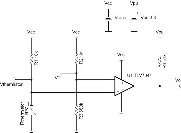
This thermal switch solution will signal low (to a GPIO pin) when a certain temperature is exceeded thus alerting when conditions are no longer optimal or device-safe. This circuit incorporates an NTC thermistor with a comparator configured in a non-inverting fashion.

Design Notes
- The resistance of an NTC thermistor drops as temperature increases.
- The TLV7041 has an open drain output, so a pull-up resistor is required.
- Configurations where the thermistor is placed near the high side of the divider can be done; however, the comparator will have to be used in an inverting fashion to still have the output switch low.
- Best practice involves placing a positive feedback resistor to add external hysteresis, for simplicity, it is not done in this example.
Design Steps
- Select an NTC thermistor,
preferably one with a high nominal resistance, R0, (resistance value
when ambient temperature, TA, is 25°C) since the TLV7041 has a very
low input bias current. This will help lower power consumption, thus reducing
the likelihood of reading a slightly higher temperature due to thermal
dissipation in the thermistor. The thermistor chosen has its R0 and
its material constant, β, listed below.
- Select R1. For high
temperature switching points, R1 should be 10 times smaller than the
nominal resistance of the thermistor. This causes a larger voltage difference
per temperature change around the temperature switching point, which helps
guarantee the output will switch at the desired temperature value.
- Select R2. Again, this
can be a high resistance value.
- Solve for the resistance of the
thermistor, Rthermistor, at the desired temperature switching point.
Using the β formula is an effective approximation for thermistor resistance
across the temperature range of -20 °C to 120 °C. Alternatively, the
Steinhart-Hart equation can be used, but several device-specific constants must
be provided by the thermistor vendor. Note that temperature values are in
Kelvin. Here T0 = 25 °C = 298.15K.
- Solve for Vthermistor at
Tsp.
- Solve for R3 with the
threshold voltage, VTH, equal to Vthermistor. This ensures
that Vthermistor will always be larger than VTH until the
temperature switching point is exceeded.
- Select an appropriate pull up
resistor, R4. Here, Vpu = 3.3V (digital high for a
microcontroller).
Design Simulations
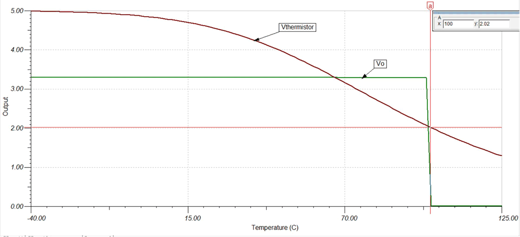
DC Temperature Simulation Results

Design References
Texas Instruments, SLVMCS1 simulation, circuit file
Design Featured Comparator
| TLV7041 | |
|---|---|
| Output Type | Open-Drain |
| Vcc | 1.6V to 6.5V |
| VinCM | Rail-to-rail |
| Vos | ±100 µV |
| VHYS | 7 mV |
| Iq | 335 nA/Ch |
| tpd | 3 µs |
| #Channels | 1 |
| TLV7041 | |
Design Alternate Comparator
| TLV1701 | |
|---|---|
| Output Type | Open-Collector |
| Vcc | 2.2V to 36V |
| VinCM | Rail-to-rail |
| Vos | ±500 µV |
| VHYS | N/A |
| Iq | 55 µA/Ch |
| tpd | 560 ns |
| #Channels | 1, 2, and 4 |
| TLV1701 | |
| TLV1701-Q1 | |