SNOAA06C July 2018 – June 2022 TMP116 , TMP117
Application Brief
Introduction
A resistance temperature detector (RTD) is a passive component whose resistance changes with temperature. RTDs are made using metals—such as platinum, copper, or nickel—and support a wide temperature range (approximately –200°C to +850°C).
The accuracy of an RTD is defined by its class. The IEC/EN60751 standard defines four RTD classes—Class C, B, A, and AA—where Class C is the least accurate and Class AA is the most accurate.
Most RTD applications use a current source to excite the RTD element and create a voltage difference across the RTD, as shown in Figure 1-1. This voltage is proportional to the resistance of the RTD and the excitation current. The voltage potential is amplified, converted to a digital output by an ADC, and is then fed into to a MCU where a lookup table is used to convert the digital output to temperature.
 Figure 1-1 Simplified RTD Circuit
RTDs in Heat Meters and CJC Systems
RTDs are one of the most widely used temperature-sensing components in industrial applications where high accuracy and longevity are desired. Heat Meters and Cold Junction Compensation (CJC) in Thermocouples are a couple of examples where RTDs are used; however, these systems can be optimized to reduce complexity and cost by replacing RTDs with temperature-sensing ICs, like the TMP117 digital temperature sensor.
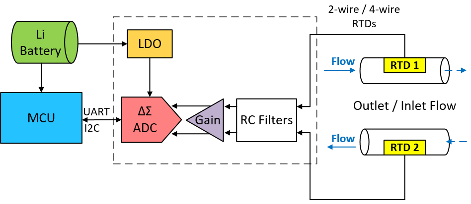
Solid state heat meters are becoming more popular for billing heat energy for residential and industrial users. Heat meters are essentially flow meters with an integrated precise differential temperature measurement subsystem to record the difference in temperature between the inlet and outlet flow. Figure 1-2 shows a block diagram of a heat meter system using RTDs.
Heat meters use the differential temperature measurement subsystem to measure temperature every few seconds. This measurement tells the user if heat is being dissipated or absorbed in the system. The system’s ability to quickly wake from power-off mode, sample the RTD temperature, and return to power-off mode extends battery life and minimizes energy consumption.
 Figure 1-2 Heat and Cold Meter With RTD
Block Diagram
Figure 1-2 Heat and Cold Meter With RTD
Block DiagramThermocouples are temperature-sensing devices that cover a large temperature range and are made by joining wires of two different metals. The output voltage is approximately proportional to the difference in temperature between the hot junction and cold junction. Remember that because the thermocouple measures a differential temperature, the temperature at the cold junction must be known to determine the temperature at the hot junction—this process is known as cold junction compensation (CJC).
PT100 RTDs are popularly used to measure the temperature of the cold junction due to their high accuracy. Figure 1-3 shows a block diagram of a cold junction compensated thermocouple system using a RTD reference.
 Figure 1-3 Cold Junction Compensation
With RTD Block Diagram
Figure 1-3 Cold Junction Compensation
With RTD Block DiagramReplacing RTD With TMP117 and TMP1826 Digital Temp Sensors
The TMP117 is a digital temperature sensor designed for low-power, high-accuracy applications. The device provides a 16-bit temperature result with a resolution of 0.0078°C and a factory-calibrated performance of ±0.2°C across –55°C to +150°C which exceeds the accuracy of a Class A RTD. The TMP1826 is a high-accuracy, single-wire compatible digital output temperature sensor. The typical accuracy of this device is ±0.1°C across the range of –20°C to +85°C. In bus-powered mode TMP1826 only requires a single connection and a ground return, which helps to simplify design and reduce cost by limiting the number of wires in the system.
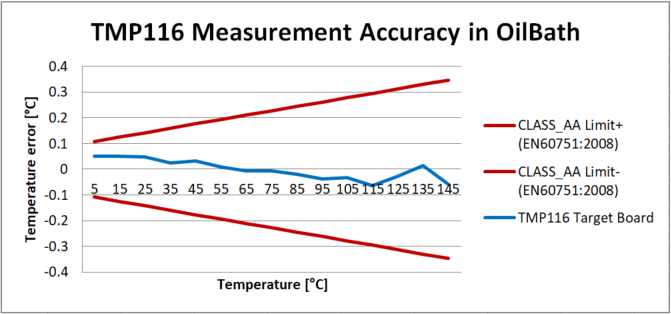
These devices provide additional simplicity over an RTD, eliminating the need for calibration, external circuitry, matched traces, and Kelvin connections. Figure 1-3 depicts the results of an oil bath experiment conducted on the TMP116, which is pin-compatible to the higher accuracy TMP117. The graph shows that even TMP116 can meet the accuracy of a Class AA RTD. These high accuracy solutions can enable smaller and more reliable real-time control systems, as fast response times will enable faster error correction when it matters most.
 Figure 1-4 TMP116 Target Board Meets
Class AA Limits Without Calibration
Figure 1-4 TMP116 Target Board Meets
Class AA Limits Without CalibrationThe TMP117 and TMP1826 feature a shutdown mode where the device aborts the currently running conversion and enters a low-power shutdown mode. Both devices can perform quick temperature conversions using the one-shot conversion mode. After completing a one-shot conversion, the device returns to low-power shutdown mode. This mode of operation minimizes power losses and the high accuracy of these devices allows for increased efficiency in real-time control systems. The accuracy and response time of the TMP117 and TMP1826 can improve efficiency of the power system by allowing operation closer to thermal limits and limiting unnecessary current throttling.
The TMP117 is comparable in accuracy to the Class AA thin-film RTD, used in Heat Meter applications, and consumes a fraction of the power of a PT100 RTD, typically used in CJC applications. Figure 1-5 and Figure 1-6 show block diagrams of Heat Meter and CJC systems using the TMP117 to replace the RTDs. The systems using the TMP117 require less components, such as delta-sigma ADCs, programmable gain amplifiers, and RC filters, than the systems using RTD elements.
Overall, the high-accuracy TMP117 and TMP1826 temperature sensors, fast conversion, and extremely low-power shutdown mode eliminate the need for multiple narrow-tolerance discrete components and integrated devices, which can save PCB space, complexity, and cost in Heat Meter and CJC systems.
 Figure 1-5 Heat and Cold Meter With
TMP117 Block Diagram
 Figure 1-6 Cold Junction Compensation
With TMP117 Block Diagram