APPLICATION BRIEF
Space-Grade, 100-krad, 100-V, High-Side Current Sensing Circuit
Design Goals
| Parameter | Value |
|---|---|
| Common-Mode Voltage (VCM) | 100 V |
| Load Current (Iload or Ishunt) | 1 A to 10A |
| Output Voltage (Vout) | 0.5 V to 5 V |
| Output Voltage Error | < 0.7% |
| Power Consumption | < 700 mW |
| Total Ionizing Dose (TID) | 100-krad (Si) |
| Single Event Latch-up (SEL) Immunity | 85 MeV·cm2/mg |
Design Description
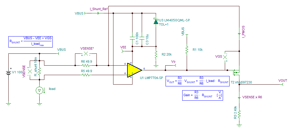
To measure the current in power system health monitoring systems, a shunt resistor is placed either at the high side or the low side of the load. However, placing it at the low side could disturb the load ground. Measuring current at the high side is more preferable in most applications. The following figure shows a high-side current sensing circuit with power supply equal to 100 V and load current varying from 1 A to 10 A. The output of this circuit ranges from 0.5 V to 5 V.
Design Notes
- The Vos of the op amp dominates the error when the load current is low. The tolerance of the shunt resistor dominates the error when the load current is high.
- Increasing R3, R5, and R6 values decreases PMOS power consumption but decreases output (VOUT) range.
- R2 dominates the power consumption in the system