SNOAA89 December 2022 AM2431 , AM2432 , AM2434
2.2 FSI RX Module
Use the following example in the FSI RX module to setup and run FSI from Arm with interrupt:
fsi_loopback_interrupt (ti.com)
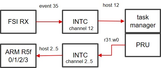
The receiving flag is sent to the PRU_INTC module by an external event when the FSI RX buffer is written.
Use the interrupt controller (INTC), data processing accelerator (task manager) and data movement accelerator (XFR2VBUS) on PRU for the receive path.
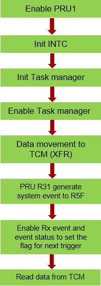
Figure 2-3 shows the design process of the FSI RX module.
 Figure 2-3 FSI RX Module Design
Process
Figure 2-3 FSI RX Module Design
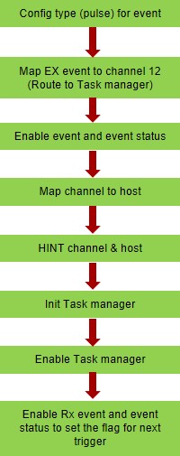
ProcessFigure 2-4 shows the specific steps for the external event trigger INTC and hit task manager.
 Figure 2-4 INTC_TASK Manager
Configuration Programming
Figure 2-4 INTC_TASK Manager
Configuration ProgrammingThe specific steps for system interrupt generate are as follows and the FSI receive data path is shown in Figure 2-5.
- Generate System Events (pulse) and mapping to R31
- Internal event 16 to 19 maps to host 2–5 (channel 2–5) which exported from PRU_ICSSG and mapped to device level-interrupt controllers
- PRU Interrupt requests to Arm
HOST 2 (Level) → R5FSS0_Core0_INTR_IN_122
…
HOST 5 (Level) → R5FSS0_Core0_INTR_IN_125
Figure 2-5 FSI Receive Data Path