SNOK006 April 2024 TPS7H6013-SP
2.3.2 Biased
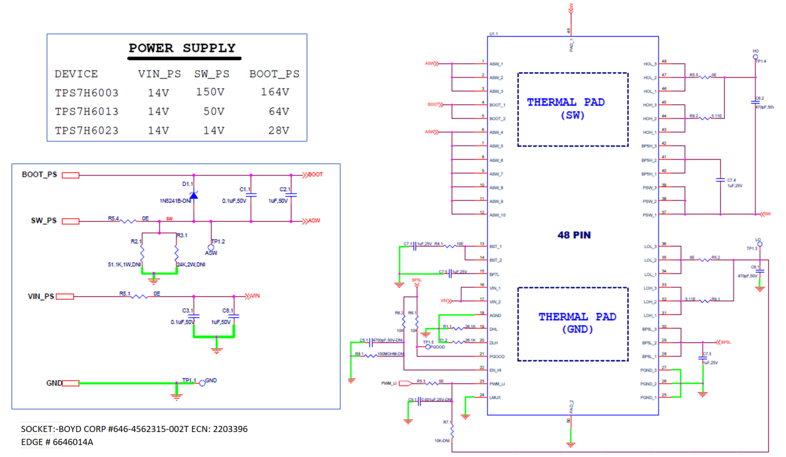
Figure 2-2 show HDR bias diagram & schematic.
Table 2-1 DUT Power Supply Bias and Vout measurements
| Power Supply Bias | ||||
|---|---|---|---|---|
| Edge Connector | BUS | Typical | Comments | |
| Power Supply | BUS A | VIN | 14VDC | 14VDC - Fixed power supply |
| BUS D | BOOT | 14VDC | 14VDCWRTSW - Floating power supply WRT to SW | |
| BUS B | ASW | 0-50V | Increase HV gradually. Recommend using safety interlock HV protection when working with high voltage. | |
| DUT Vout Measurements | ||||
| VOUT Test Points | TP_PGOOD | ON | 5V | LS is ON |
| TP_LO | PWM_LI | 1.8V | PWM mode | |
| TP_HO | PWM_LI DC WRT ASW | 3.51V | PWM mode | |
| TP_SW | SW = PSW = ASW | 0-50V | SW = PSW = ASW | |
| PWM_LI | DUT Mon | 1.85V | DUT monitor edge connector | |
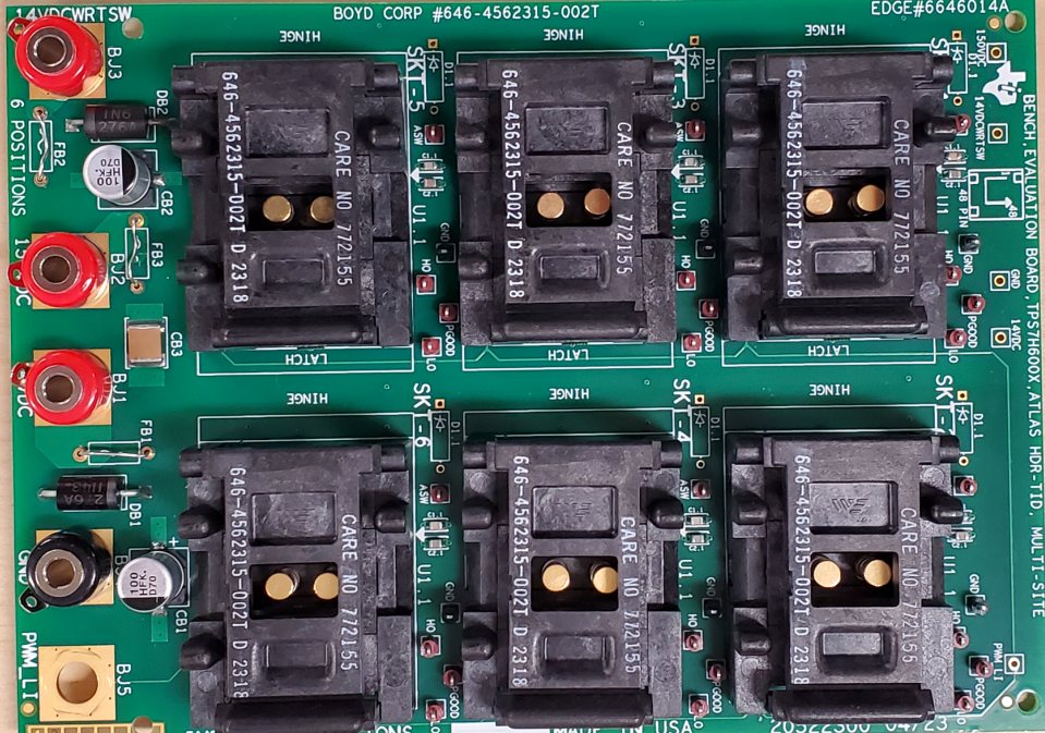
 Figure 2-1 HDR TID Hardware
 Figure 2-2 HDR TID Bias Diagram