SNOU176B October 2020 – March 2022
PRODUCTION DATA
- Trademarks
- 1 General TI High Voltage Evaluation User Safety Guidelines
- 2 Introduction
- 3 LMG342XEVM-04X Schematic
- 4 Mother Board Schematic
- 5 Recommended Footprint
- 6 Test Equipment
- 7 Test Procedure When Paired With LMG342X-BB-EVM
- 8 Test Procedure When Paired With LMG34XX-BB-EVM
- 9 Bill of Materials
- 10Revision History
8.1 Setup
The following procedure is recommended to set up the LMG34XX-BB-EVM with the LMG342XEVM-04X. The inductor on the LMG34XX-BB-EVM is capable of up to 1.7-kW operation. For a higher power level, use an external inductor.
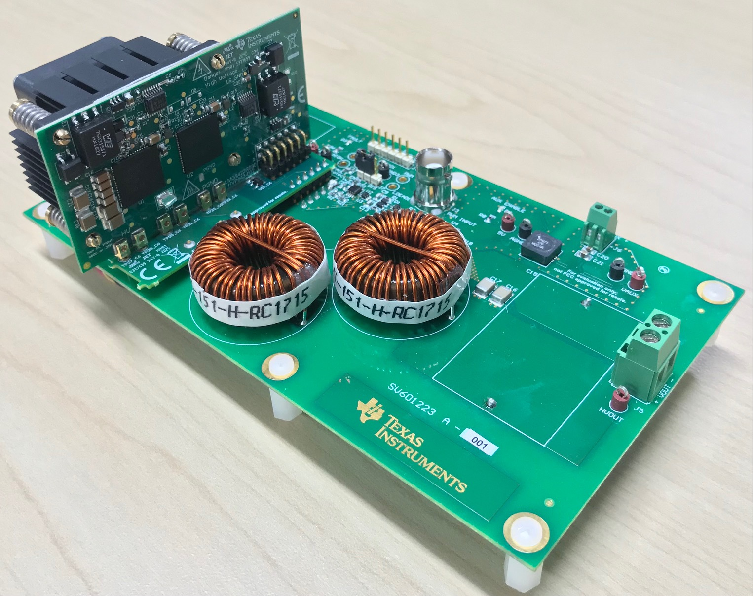
Figure 8-1 shows the LMG342XEVM-04X connected to the LMG34XX-BB-EVM.
Note: TI provides a custom interposer board
that must be used when the LMG342XEVM-04X is paired with the LMG34XX-BB-EVM. The
interposer board is not needed with LMG342x-BB-EVM.
 Figure 8-1 LMG342XEVM-04X Connected
to the LMG34XX-BB-EVM
Figure 8-1 LMG342XEVM-04X Connected
to the LMG34XX-BB-EVMFigure 8-2 shows the LMG34XX-BB-EVM power and probe connection points.
 Figure 8-2 Recommended Connection
Points
Figure 8-2 Recommended Connection
PointsPCB Notes:
- A: Probe points for gate drive logic
- B: 100-mil header for PWM input, PWM signals to LMG342XEVM-04X and FAULT output
- C: BNC connector for PWM input
- D: 12-V bias supply input
- E: FAULT protection option header
- F: Power stage high voltage input
- G: Probe point for power stage switch node
- H: Power stage high voltage output
To connect the LMG342XEVM-04X to the LMG34XX-BB-EVM:
- Connect the oscilloscope or multimeter probes to the desired test points in A or G.
- Connect the 12-V bias supply, connect load to output, and connect the input supply to input.
- Connect the function generator to either the BNC connector PWM input at C or 100-mil header connector input at pin 6 (PWM) and pin 5 (GND) at B.
- Connect 12-V bias supply to the fan attached on the EVM, or enable an external fan to direct airflow across the heat sink attached to the LMG342XEVM-04X.