SNOU204 October   2024


  1.   1
  2.   Description
  3.   Get Started
  4.   Features
  5.   Applications
  6.   6
  7. 1Evaluation Module Overview
    1. 1.1 Introduction
    2. 1.2 Kit Contents
    3. 1.3 Specification
    4. 1.4 Device Information
  8. 2Hardware
    1. 2.1 Overview
    2. 2.2 Perforations and Connectivity
    3. 2.3 Status LEDs (D3, D5, D6) and Subregulator
    4. 2.4 Programming Header
    5. 2.5 BSL Button
    6. 2.6 Remote BJT - Q1
    7. 2.7 Address Jumpers
    8. 2.8 Current Measurement - SEL Measurement
  9. 3Software
    1. 3.1 Software Installation
      1. 3.1.1 Live Software on dev.ti.com
      2. 3.1.2 Download from dev.ti.com
    2. 3.2 Home Tab
    3. 3.3 Data Capture Tab
    4. 3.4 Registers Tab
  10. 4Hardware Design Files
    1. 4.1 Schematic
    2. 4.2 PCB Layout
    3. 4.3 Bill of Materials
  11. 5Additional Information
    1. 5.1 Trademarks

Overview

The EVM is divided into two sections: the controller section and the breakable sensor section. The breakable sensor section can be detached to use the sensor in the following scenarios:

  • Using the controller section with the sensor section connected by soldered wires and connectors to evaluate the sensor far from the controller and PC at extreme temperatures or other conditions.
  • Using the sensor section with the user's system by interfacing through I2C with the TMP9R01.
  • Using the controller section with TMP9R01 sensors in the user's system.

The EVM sections and some components that must be identified by the user to understand the purpose and use are highlighted in Figure 2-1. The components are further explained in detail in the sections below.
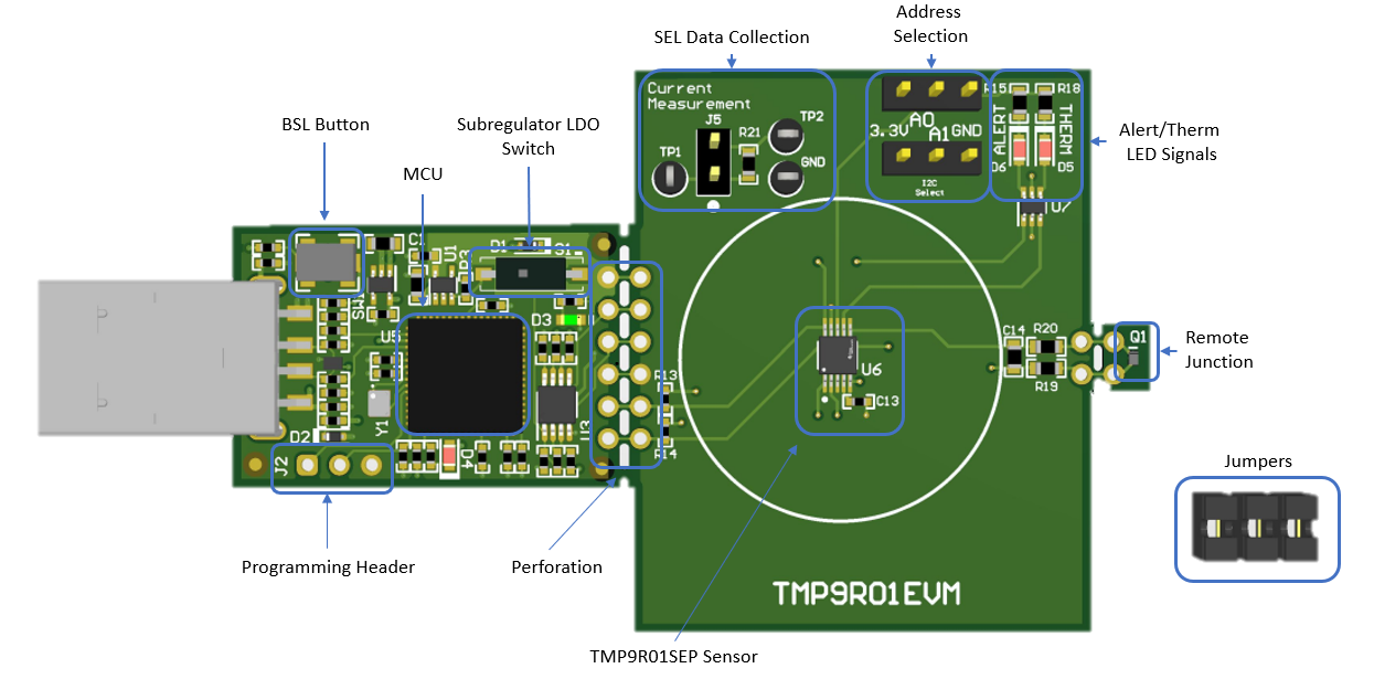
TMP9R01EVM TMP9R01EVM Board
                    Sections Figure 2-1 TMP9R01EVM Board Sections