SNOU204 October 2024
2.8 Current Measurement - SEL Measurement
This EVM provides two approaches in measuring the total quiescent current of the TMP9R01 device. Within this section of the EVM, there is a jumper and three test points: TP1, TP2, and GND.
Option 1: Measure the current through the resistor with known voltage measurements of TP1 and TP2. The jumper is in parallel with a resistor. To take advantage of this option, users need to remove the jumper and repopulate the resistor R21 with a value of your choice.
Option 2: Using a SMU to supply voltage and measure current through TP2 and GND. To take advantage of this option, remove R21 resistor, switch off the USB power through the Subregulator switch and supply TP1 and TP2 with the same voltage within the range of 1.7V to 3.6V.
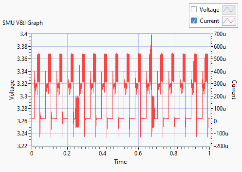
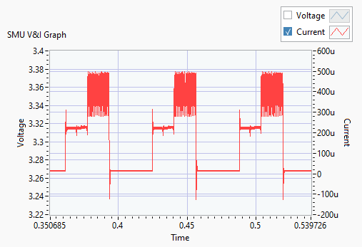
When measuring current through this device, the following images show what to expect for the current output. There are different current ranges for what mode the device is in. Shutdown mode consumes the least amount of power vs active conversion mode consumes the most amount of power.
| TYP (µA) | MAX (µA) | ||
|---|---|---|---|
| Iq | Active conversion, local sensor | 240 | 375 |
| Active conversion, remote sensor | 400 | 600 | |
| Standby mode (between conversions) | 15 | 35 | |
| Shutdown mode, serial bus inactive | 3 | 8 | |
| Shutdown mode, serial bus active, fs = 400kHz | 90 | ||
| Shutdown mode, serial bus active, fs = 2.17MHz | 350 |

