SNOU205 December 2024 LMG2650
2.5.1 Setup
The inductor on LMG342X-BB-EVM is capable of around 3kW operation. For higher power levels, use an external inductor.
TI recommends the following procedure to set up the LMG342X-BB-EVM with the LMG2650EVM-100:
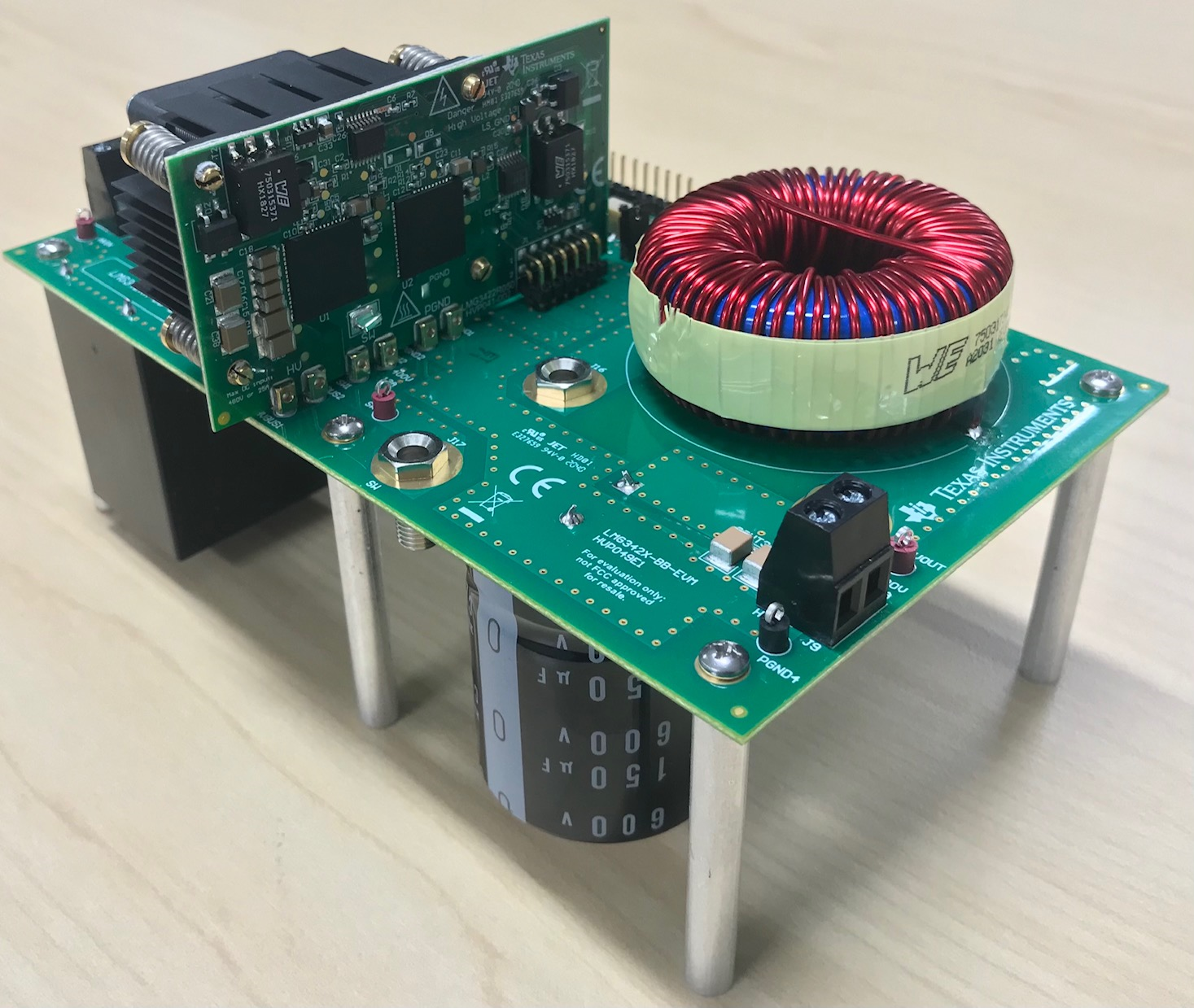
- Connect the LMG2650EVM-100 to LMG342X-BB-EVM as shown in step 2; see Figure 2-5. The area for connection on the mother board is shown in Figure 2-6.
- Install the LMG342X-BB-EVM inside a ventilated HV safety box.
- Disconnect jumper J13 to enable the 12V to 5V onboard power conversion.
- Disconnect jumper J12.
- If the onboard complementary PWM generation circuits are used to generate the dead time, then connect pin 2 to pin 3 for header J7 and J14 with jumpers. Under this configuration, only one PWM signal is required and can be connected to either J3 or J8.
- If two complementary PWM signals with dead time are provided to J3 (high-side PWM) and J8 (low-side PWM), then connect pin 1 to pin 2 for header J7 and J14 (pin 1 of J7 and J14 are indicated in Figure 2-6). This action allows the two PWM signals to directly control the high-side and low-side devices.
- If fault interlock feature is desired, then connect jumper J10 and J11. Otherwise, disconnect them and the PWM signals can always pass through to the devices.
- Set the signal generator to a desired frequency and duty cycle (that is, 100kHz, and 50% duty cycle). 5V for high input and 0V for low input.
- Connect the signal generator output to the LMG342X-BB-EVM PWM input as shown in Figure 2-6.
- Connect 12V, 2A DC power supply to the LMG342X-BB-EVM 12V bias supply as shown in Figure 2-6.
- Connect the high voltage power supply to the LMG342X-BB-EVM high voltage input for buck mode (high voltage) as shown in Figure 2-6.
- Provide 12V bias supply to fan by connecting the 3-pin power cord from fan to J15.
 Figure 2-5 LMG342X-BB-EVM Motherboard With
LMG2650EVM-100
 Figure 2-6 Connector and LEDs on the
LMG342X-BB-EVM