SNVA055I July 2002 – January 2022 LM2642
3 Powering Up
Before powering up the LM2642 evaluation board, all external connections should be verified. The power supply input must be turned off and connected with proper polarity to the VIN post, also marked as P1. The channel 1 and channel 2 loads should be connected at the VOUT posts, marked as P2 and P3. Any type of load is acceptable up to 2 A. The load can be on or off at start-up. Output voltage can be monitored with a DVM or oscilloscope by connecting probes to the VOUT posts, P2 and P3. The GND posts are provided primarily for scope probe ground connections. The PGOOD signal can be monitored with a scope probe or DVM at the PGOOD test pin.
Once all connections have been verified, input power can be applied. The input voltage must be set between 4.5 V and 20 V. The enable switches for each channel, ON1 and ON2, can be used to turn on the evaluation board once the input power is on. Each channel can be enabled or disabled independently. The switches can also be left on for enabling the evaluation board directly from the power supply input.
 Figure 3-1 Complete Evaluation Board
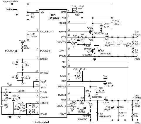
Schematic
Figure 3-1 Complete Evaluation Board
Schematic| Part # | Value | Supplier |
|---|---|---|
| C1 | Cer Cap 1 F 50 V Y5V 0805 | Taiyo Yuden UMK212F105ZG |
| C2 | Cer Cap 47 nF 50 V 10% 0805 | Vishay VJ0805Y473KXA |
| C3 | Cer Cap 10 nF 50 V 10% 0805 | Vishay VJ0805Y103KXA |
| C4 | Cer Cap 10 nF 50 V 10% 0805 | Vishay VJ0805Y103KXA |
| C5 | Cer Cap 220 pF 25 V 10% 0805 | Vishay VJ0805Y221KXA |
| C6 | Cer Cap 6.8 nF 50 V 10% 0805 | Vishay VJ0805Y682KXA |
| C7 | Cer Cap 6.8 nF 50 V 10% 0805 | Vishay VJ0805Y682KXA |
| C8 | Cer Cap 470 pF 25 V 10% 0805 | Vishay VJ0805Y471KXA |
| C9 | Cer Cap 4.7 µF 10 V X7R 1206 | Taiyo Yuden LMK316BJ475ML |
| C10 | Cer Cap 1 µF 10 V X7R 0805 | Taiyo Yuden LMK212BJ105ZG |
| C11 | Cer Cap 10 nF 50 V 10% 0805 | Vishay VJ0805Y103KXA |
| C12 | Cer Cap 10 µF 35 V Y5V 1210 | Taiyo Yuden GMK325F106ZH |
| C13 | Electro Cap 33 µF 50 V | Panasonic EEU-FC1H330 |
| C14 | Cer Cap 0.1 µF 50 V 10% 0805 | Vishay VJ0805Y104KXA |
| C15 | Cer Cap 0.1 µF 50 V 10% 0805 | Vishay VJ0805Y104KXA |
| C16 | Cap-SP 150 µF 6.3 V 20% | Panasonic EEFUEOJ151R |
| C17 | Not Installed | |
| C18 | Cer Cap 10 nF 50 V 10% 0805 | Vishay VJ0805Y103KXA |
| C19 | Cer Cap 10 µF 35 V Y5V 1210 | Taiyo Yuden GMK325F106ZH |
| C20 | Electro Cap 33 µF 50 V | Panasonic EEU-FC1H330 |
| C21 | Cer Cap 0.1 µF 50 V 10% 0805 | Vishay VJ0805Y104KXA |
| C22 | Cer Cap 0.1 µF 50 V 10% 0805 | Vishay VJ0805Y104KXA |
| C23 | Not Installed | |
| C24 | Cap-SP 150 µF 6.3 V 20% | Panasonic EEFUEOJ151R |
| D1 | Switching Diode-Dual 70 V 200 mA BAW56F | Fairchild BAW56F |
| D2 | Schottky Diode 40 V 1A | On Semiconductor MBRS140T31A |
| D3 | Schottky Diode 40 V 1A | On Semiconductor MBRS140T31A |
| L1 | Inductor 6 µH | Sumida CEP125-6R0MC |
| L2 | Inductor 4.3 µH | Sumida CEP125-4R3MC |
| Q1 | Si9936DY | Vishay |
| Q2 | Si9936DY | Vishay |
| R1 | Res 220 kΩ 0.1W 5% 0805 | Vishay CRCW0805224J |
| R2 | Res 20 kΩ 0.1W 5% 0805 | Vishay CRCW0805203J |
| R3 | Res 20 kΩ 0.1W 5% 0805 | Vishay CRCW0805203J |
| R4 | Res 4.7 Ω 0.1W 5% 0805 | Vishay CRCW08054R7J |
| R5 | Res 13.7 kΩ 0.1W 1% 0805 | Vishay CRCW08051372F |
| R6 | Res 4.7 Ω 0.1W 5% 0805 | Vishay CRCW08054R7J |
| R7 | Res 0 Ω 0.1W 5% 0805 | Vishay CRCW08050RJ |
| R8 | Res 20.5 kΩ 0.1W 1% 0805 | Vishay CRCW08052052F |
| R9 | Res 20 kΩ 0.1W 1% 0805 | Vishay CRCW08052002F |
| R10 | Res 13.7 kΩ 0.1W 1% 0805 | Vishay CRCW08051372F |
| R11 | Res 4.7 Ω 0.1W 5% 0805 | Vishay CRCW08054R7J |
| R12 | Res 0 Ω 0.1W 5% 0805 | Vishay CRCW08050RJ |
| R13 | Res 9.09 kΩ 0.1W 1% 0805 | Vishay CRCW08059092F |
| R14 | Res 20 kΩ 0.1W 1% 0805 | Vishay CRCW08052002F |
| S1 | Switch SPST 0.4VA 28 V AC/DC A12AB | NKK A12AB |
| S2 | Switch SPST 0.4VA 28 V AC/DC A12AB | NKK A12AB |
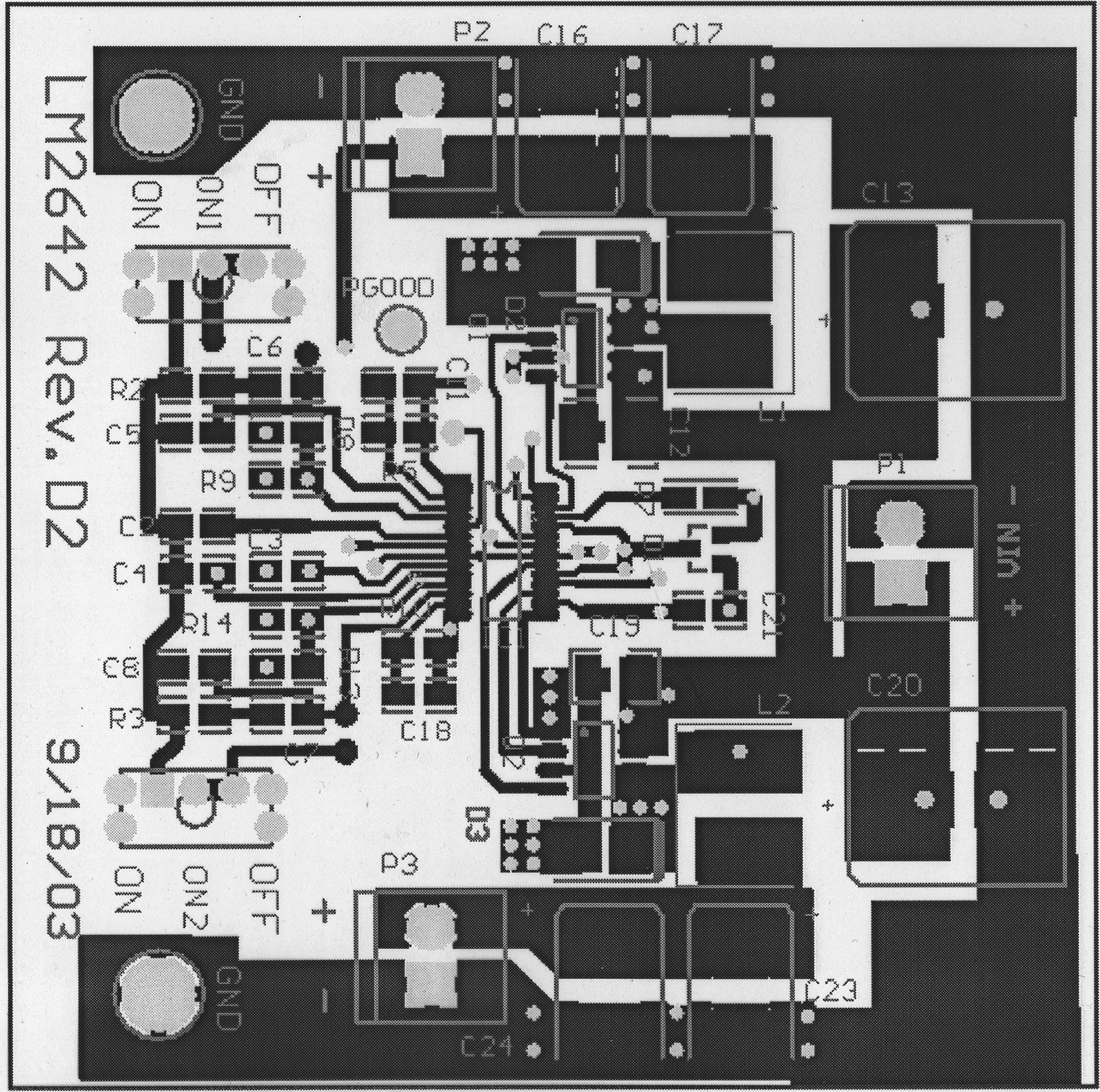
 Figure 3-2 Top Layer
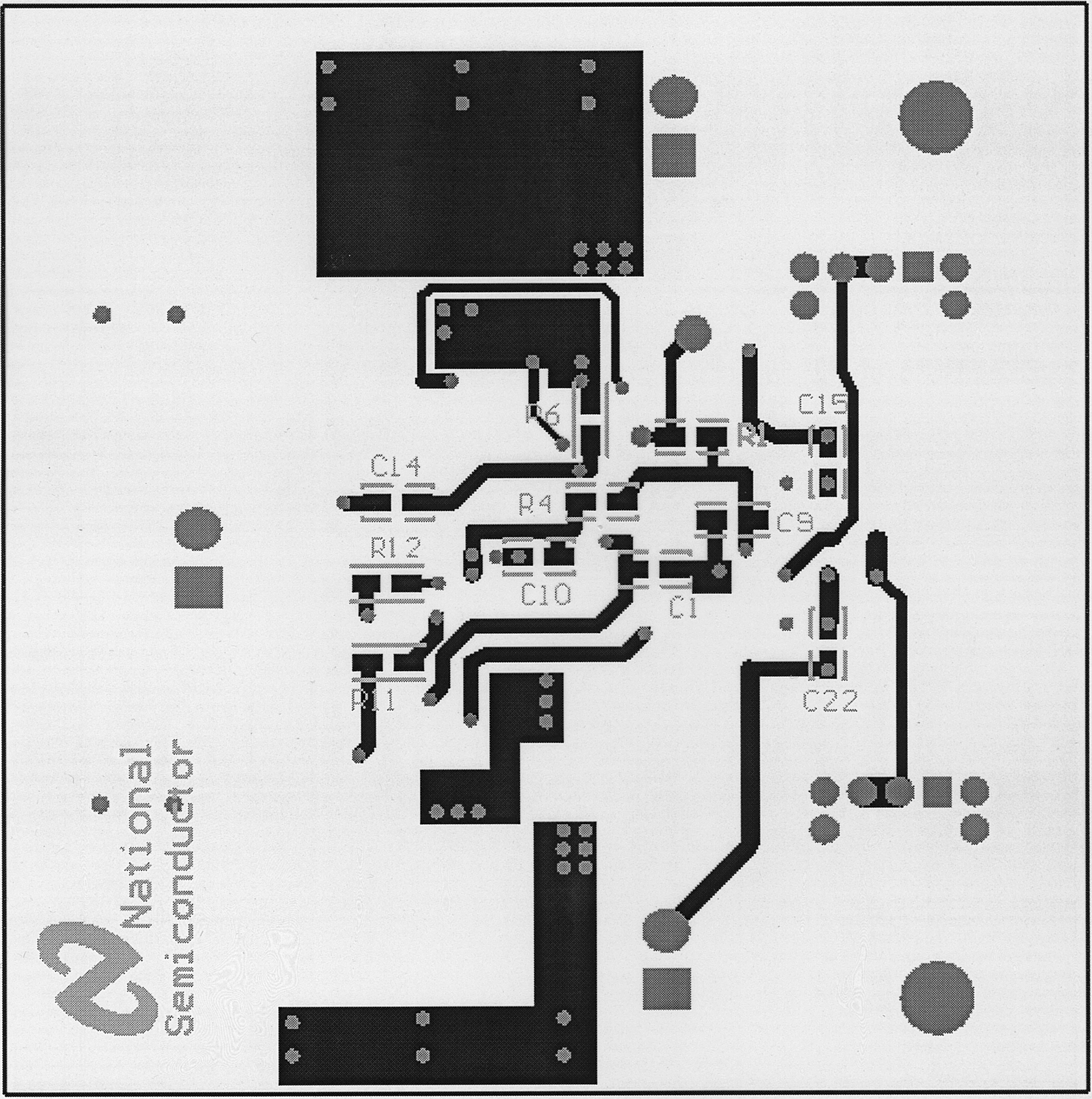
 Figure 3-3 Bottom Layer