SNVA389B July 2009 – February 2022 LM3000
3.3 Tracking
The LM3000 evaluation board is configured such that VOUT2 tracks VOUT1, while VOUT1 voltage increases with a rate determined by the value of C17, the soft-start capacitor for VOUT1 (Condition 1). This configuration will not allow VOUT2 to be turned on independently without turning on VOUT1. In order to track VOUT1, the TRK2 pin should be connected to a divider junction between R14 and R15 through R26.
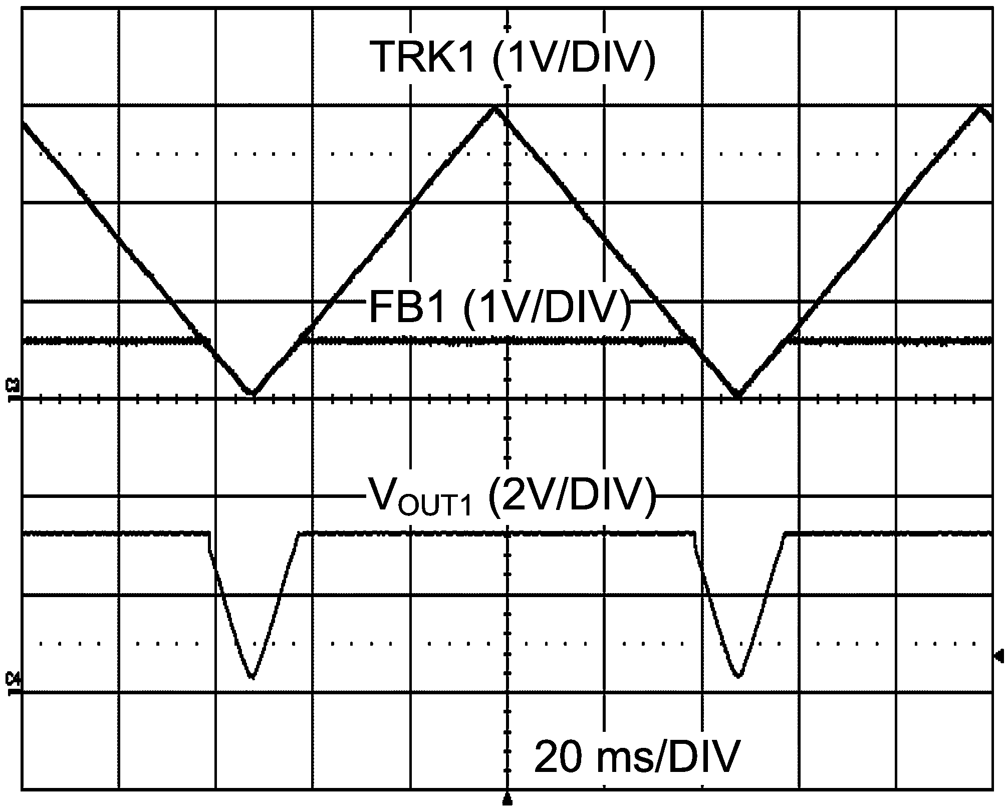
When both outputs are used to track an external source (Condition 2), then R25, R26, and R28 should be left open and a 10-Ω resistor should be added into R24 and R27.
If no tracking feature is required, both TRK1 and TRK2 should then be tied to VDD in order to soft start each output voltage based on a soft-start capacitor value (Condition 3). This can be done by keeping R24, R26, and R27 open while adding a 10-Ω resistor onto R25 and R28.
Please note that the slew rate of track signal should be lower than the soft-start slew rate, which is set by soft-start capacitor value.
The following are the summary of different tracking configuration on the LM3000EVAL board:
| Condition | R24 | R25 | R26 | R27 | R28 |
|---|---|---|---|---|---|
| 1 | Open | 10 Ω | 10 Ω | Open | Open |
| 2 | 10 Ω | Open | Open | 10 Ω | Open |
| 3 | Open | 10 Ω | Open | Open | 10 Ω |
 Figure 3-2 Tracking with an External Ramp for 3.3-V
Output