SNVA941A June 2020 – November 2022 LM5156 , LM5156-Q1 , LM51561 , LM51561-Q1 , LM51561H , LM51561H-Q1 , LM5156H , LM5156H-Q1
- How to Design a Boost Converter Using the LM5156
- 1LM5156 Design Example
- 2Example Application
-
3Calculations and Component Selection
- 3.1 Switching Frequency
- 3.2 Inductor Calculation
- 3.3 Current Sense Resistor Calculation
- 3.4 Inductor Selection
- 3.5 Diode Selection
- 3.6 MOSFET Selection
- 3.7 Output Capacitor Selection
- 3.8 Input Capacitor Selection
- 3.9 UVLO Resistor Selection
- 3.10 Soft-Start Capacitor Selection.
- 3.11 Feedback Resistor Selection
- 3.12 Control Loop Compensation
- 3.13 Efficiency Estimation
- 4Component Selection Summary
- 5Small-Signal Frequency Analysis
- 6Revision History
3.11 Feedback Resistor Selection
The feedback resistors (RFBT, RFBB) set the regulated load voltage by comparing the scaled voltage to the internal voltage reference. To help limit the bias current of the feedback resistor divider, RFBT is selected to be 49.9 kΩ. Equation 22 is used to calculate the value of RFBB.
Equation 22. 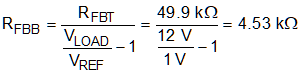
RFBB is selected to be 4.53 kΩ.