SNVA951 November 2020 LM61460-Q1 , LM63615-Q1 , LM63625-Q1 , LM63635-Q1 , LMR33620-Q1 , LMR33630-Q1
3.4.1 Thermal Metrics
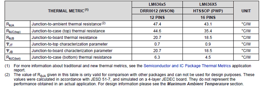
Most data sheets include a value for θJA, along with other information, in the thermal characteristics table. Figure 3-1 shows an example from the automotive qualified LM636x5-Q1 3.5-V to 36-V, 1.5-A, and 2.5-A Automotive Step-down Voltage Converter Data Sheet.
 Figure 3-1 Typical
Thermal Metrics From Device Data Sheet
Figure 3-1 Typical
Thermal Metrics From Device Data SheetThe value of θJA (or RθJA) given in this table is taken under very specific conditions, that do not necessarily apply to the real application. Typically, the value of θJA will be quite a bit larger than what can be achieved with proper PCB layout. Therefore the table value cannot be used for design purposes; its main use is in comparing between different regulators and different packages. As will be shown, the other metrics in the table can be very helpful. For packages with a Die Attach Paddle (DAP) the value of θJC (or RθJC(bott)) for the bottom of the device is also important. Equation 4 shows how to use this parameter.

In this equation, θSA is the thermal resistance from the heat sink to the ambient air. Usually, the value of θSA is not known and θJA is the true value of interest (Equation 1). However, some calculator tools require θJC when estimating the overall thermal performance. Also, a smaller value of θJC, will help to reduce the overall θJA.
You will notice in the
table that there are those metrics termed as "thermal resistance"
and those termed as "thermal parameters". The thermal
resistance values are defined and measured assuming
that all of the power flows in the path indicated by the metric
name. As an example, with θJC (or RθJC(bott))
it is assumed that all the power is flowing from the junction to the
bottom DAP. These metrics are most important when designing the
thermal management of the overall system from the junction to the
ambient environment. Thermal parameters are defined and
measured assuming that only some of the power is flowing in the path
indicated by the metric name. As an example, the parameter
ΨJT is used to calculate the junction temperature
by measuring the top case temperature with a thermocouple or thermal
camera. This calculation is discussed in Section 8.1. Essentially
the "Ψ" parameters are used when evaluating and testing the system
based on measurements. The "θ" resistances are used when designing
or calculating the thermal performance of the system. Suppose a heatsink is used on the top of the package, rather than
using the PCB through the bottom DAP connection. A safe assumption would be that most, if not all, of the heat is going through the top
heatsink. In this case use the resistance,
RθJC(top), rather than the ΨJT
parameter to calculate the overall performance. Even though both the
metrics indicate heat flow from "junction" to "top", the correct
value to use would be the
RθJC(top). The parameter ΨJB can
also be useful. A measurement of the board temperature,
TB, could be used to estimate TJ using
Equation 6. See Semiconductor
and IC Package Thermal Metrics to get a
much more detailed explanation of thermal metrics and how they are
measured and used.