SNVA964 June 2020 LP8866-Q1
1.1 Design Overview
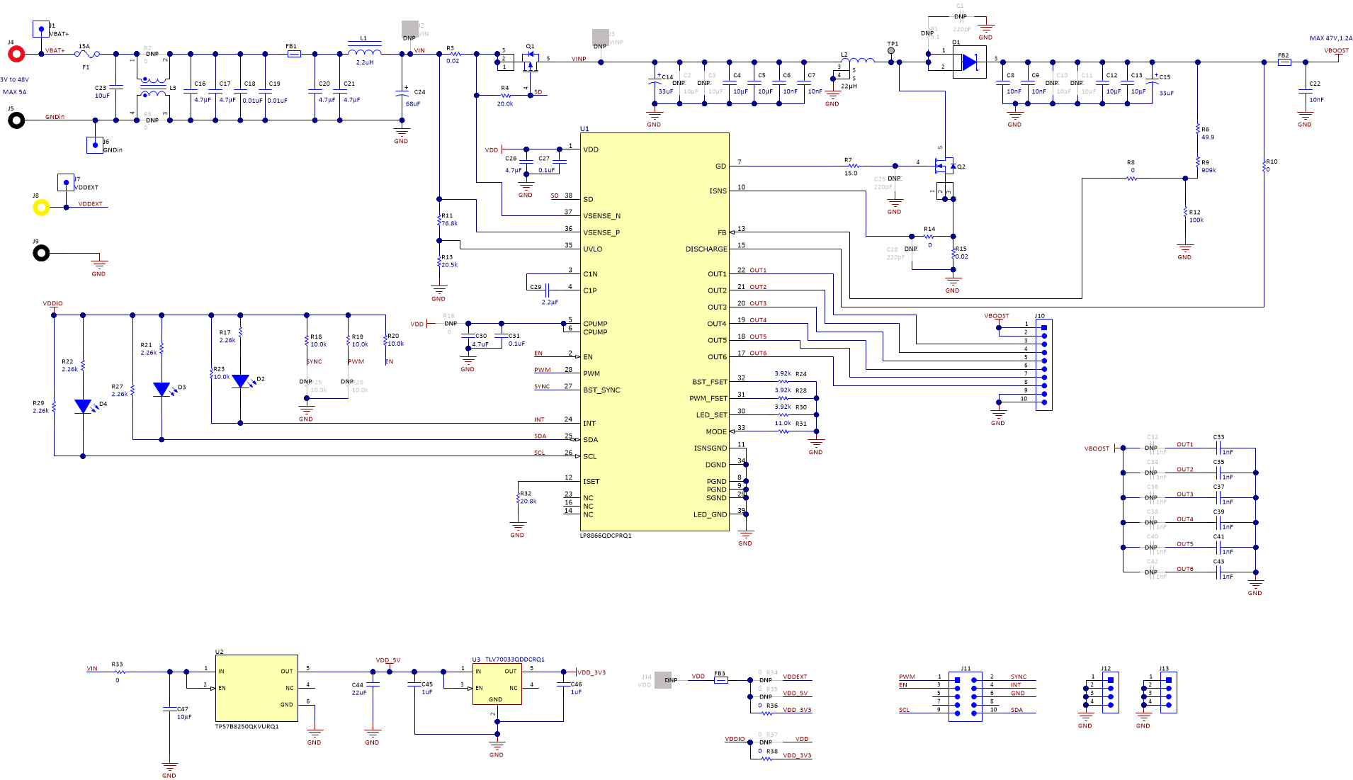
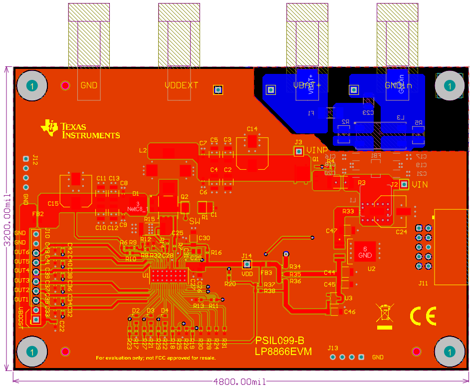
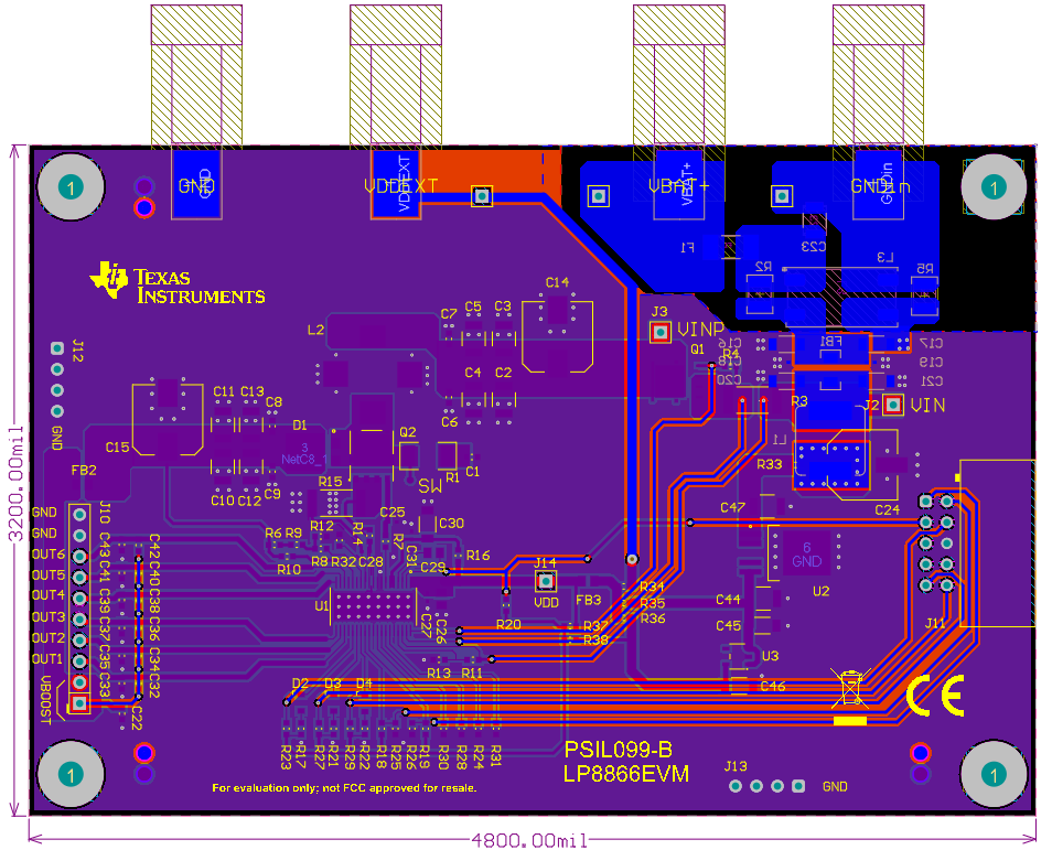
The LP8866-Q1 is an automotive high-voltage LED driver for automotive infotainment, clusters, HUD and other automotive display LED backlight applications. It integrates a boost controller and six current sinks. A reference board is built to evaluate its Electromagnetic Interference (EMI) performance. The schematic and board layout are shown in Figure 1, Figure 2 and Figure 3. A four-layer board is used with two internal ground planes. A LED load board is connected to the LP8866-Q1 driver board with seven 20-cm long jumper wires to simulate the load configuration in the real application.
 Figure 1. LP8866-Q1 Reference Design Schematic
  Figure 2. Layout - Top Layer
 Figure 3. Layout - Bottom Layer