SNVAA16 May 2021 TPS548A28 , TPS548A29 , TPS548B28 , TPS54JA20 , TPS54JB20
4 Power Loss of Multi-Rail Point-of-Load System
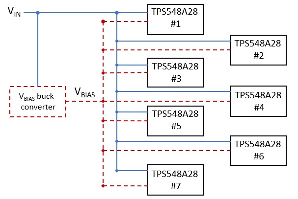
Many applications use multiple DC/DC converters in a point-of-load architecture. Figure 4-1 shows 7 rails using the TPS548A28 accepting external 3.3-V or 5-V VBIAS voltages from either a seperate step-down converter or a separate power supply rail already on the circuit board. The TPS548A29 with a 4.5-V internal LDO may also be used in its place to compare the TPS548A28 power loss across different output current levels.
Using the TPS548A28 with an external 5-V bias voltage, compared to the TPS548A29 4.5-V internal LDO saves 1.03-W at 12-A. Efficiency gains are realized from the reduced power losses of the overridden internal LDOs . The power loss of each internal LDO is approximately the bias current IVCC (20-mA) multiplied by the voltage-drop (7-V) from the 7 DC/DC converters in the multi-rail system, and the calculated value of approximately 0.98-W correlates with the measurement at 12-A. Alternatively, the TPS548A28 with an external 3.3-V bias voltage compared to the TPS548A29 4.5-V internal LDO saves only 100-mW of power. In this example, the higher gate-drive voltage of the TPS548A29 improves the MOSFET RDS(on) conduction losses of Equation 5, compared to the TPS548A28 and external 3.3-V bias, but the internal LDO losses realized are still higher than the conduction loss savings. Table 4-1 summarizes the power loss measurements at various loads and configurations under the specified conditions. Table 4-2 shows the difference in MOSFET resistance depending on the applied gate-drive voltage. Both devices have the same integrated power stage. A higher gate-drive voltage provides lower RDS(ON) for higher efficiency and lower power losses.
Table 4-3 compares the TPS548A28 with an internal 3-V bias volatge and an externally applied 5-V bias. At 10-A, there is a significant 1.56 W power loss savings between the TPS548A28 with a 3-V internal LDO to an externally applied 5-V bias voltage. MOSFET conduction loss savings are more prominent than the internal LDO power loss savings considering all 7 DC/DC converters together. At lower currents, the power loss improvements are less significant because conduction losses are less significant. At 1-A load, the savings from the external 5-V bias configuration saves only 30mW and at 5-A is 530mW. MOSFET gate-drive voltage and output current need to be considered when realizing power loss savings.
 Figure 4-1 Multiple Rail System Using the
TPS548A28 with External VBIAS Voltage
Figure 4-1 Multiple Rail System Using the
TPS548A28 with External VBIAS Voltage12-V input, 1-V output, fsw = 600 kHz, L=1 uH / 2.55 mΩ
| Device | Bias Voltage | 1-A | 5-A | 10-A |
|---|---|---|---|---|
| TPS548A28 | Internal 3-V | 1.98 | 4.13 | 11.2 |
| TPS548A28 | External 5-V | 1.95 | 3.6 | 9.64 |
| Device | Parameter | Description | Conditions | Typ. | Units |
|---|---|---|---|---|---|
| TPS548A28 | RDS(ON)HS |
High-side MOSFET on-resistance |
BOOT–SW = 3 V |
10.2 |
mΩ |
| RDS(ON)LS | Low-side MOSFET on-resistance |
VCC = 3 V |
3.1 |
mΩ | |
| TPS548A29 | RDS(ON)HS | Low-side MOSFET on-resistance | BOOT–SW = 4.5 V |
8.4 |
mΩ |
| RDS(ON)LS | Low-side MOSFET on-resistance |
VCC = 4.5 V |
2.6 |
mΩ |
12-V input, 1-V output, fsw = 600 kHz, L=1 uH / 2.55 mΩ
| Device | Bias Voltage | 1-A | 5-A | 10-A |
|---|---|---|---|---|
| TPS548A28 | Internal 3-V | 1.98 | 4.13 | 11.2 |
| TPS548A28 | External 5-V | 1.95 | 3.6 | 9.64 |