SNVAA70 june 2023 LM5176 , LM5176-Q1
3.3 Start-Up
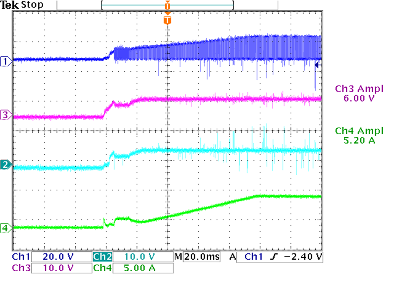
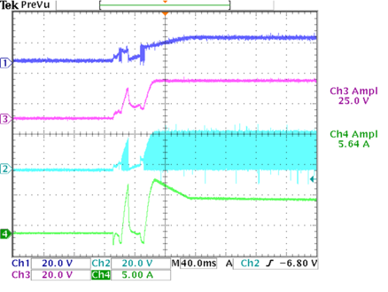
Figure 3-11 and Figure 3-12 show the start-up of LM5176 at different output voltages. In this application note, the design starts up well under the voltage difference across the TEC element within 10 V. As the TEC element is connected between the Vin and Vout of the LM5176, the TEC element biases the Vout. Thus, TI recommends setting the initial Vout close to Vin for a more stable start-up and then regulate the Vout to required voltage.
CH1: SW1, CH2: SW2, CH3: VOUT,
CH4: I TEC
CH1: SW1, CH2: SW2, CH3: VOUT,
CH4: I TEC Figure 3-11 15-V Input, 5-V Output. CH1: SW1, CH2: SW2, CH3: VOUT,
CH4: I TEC
 Figure 3-11 15-V Input, 5-V Output. CH1: SW1, CH2: SW2, CH3: VOUT,
CH4: I TEC
Figure 3-11 15-V Input, 5-V Output. CH1: SW1, CH2: SW2, CH3: VOUT,
CH4: I TECCH1: SW1, CH2: SW2, CH3: VOUT,
CH4: I TEC Figure 3-12 15-V Input, 25-V Output. CH1: SW1, CH2: SW2, CH3: VOUT,
CH4: I TEC
 Figure 3-12 15-V Input, 25-V Output. CH1: SW1, CH2: SW2, CH3: VOUT,
CH4: I TEC