SNVAA84 October 2023 LMR36506
3.3 Thermal Behavior
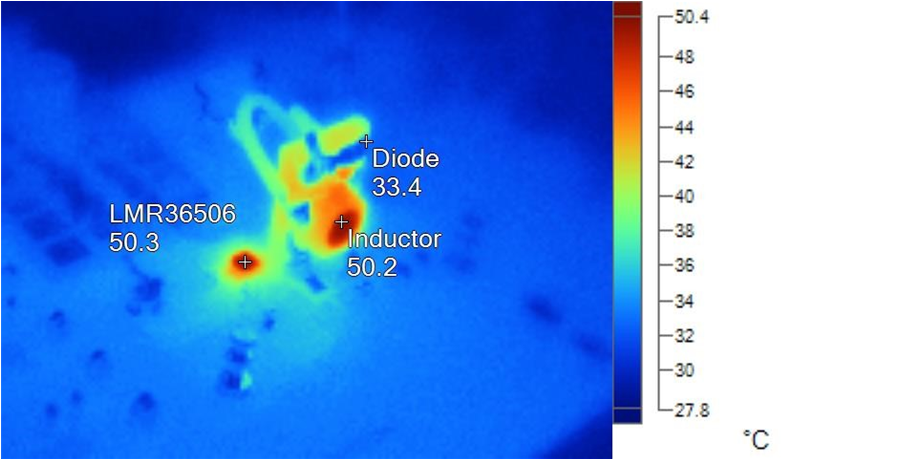
The thermal test is conducted on a modified LMR36506RFRPER EVM board to make sure that the components can withstand the industrial temperature range. The temperatures of three major components such as Inductor, DC/DC converter and the diode are observed for the minimum and maximum VIN, as shown in Figure 3-3 and Figure 3-12, respectively.
The temperature of an inductor and DC/DC converter are in the range of 48°C with the VIN of 16 V and a load of 175 mA applied on both output channels, while the diode remains at 32.6°C. With the VIN of 35 V and load of 250 mA on both output channels, the temperature of an inductor and DC/DC converter are in the range of 50°C while the diode remains at 33.4°C. This thermal output demonstrates the thermal metrics of the board, which are well within the industrial temperature range.
 Figure 3-3 Thermal Behavior at 16-V
Vin, 175-mA Load on Both Rails
 Figure 3-4 Thermal Behavior at 35-V
Vin, 250-mA Load on Both Rails