SNVAA87 august 2023 LMR38020
4.5 Short Circuit
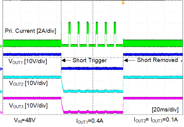
The LMR38020 enters hiccup protection mode when the primary side output is shorted to ground, as the waveform shown in Figure 4-13. When the short condition is removed, the converter auto-recovered.
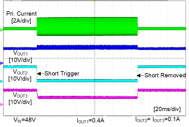
However, when the secondary side output is shorted to ground, the device does not shutdown or enter hiccup mode. Due to the negative peak current protection mode (start a new cycle when the IL_NEG is hit), the LMR38020 operates under very high fsw, the inductor and the silicon can be hot. This needs to be avoided during normal operation as hinted in Section 3.3.
 Figure 4-13 Short Circuit- Primary
Output
 Figure 4-14 Short Circuit- Secondary
Output