SNVAA94 November 2023 LM5113-Q1 , LMG1205 , LMG1210
- 1
- Abstract
- Trademarks
- 1 Introduction
- 2 Bootstrap Overcharge
- 3 Modeling Bootstrap Overcharge
- 4 Changing Bootstrap Components
- 5 Zener Diode Method
- 6 Schottky Diode Method
- 7 Overvoltage Clamp Method
- 8 Active Switch Method
- 9 Synchronous GaN Bootstrap Method
- 10Other Methods of Preventing Bootstrap Overcharge
- 11Summary
- 12References
4 Changing Bootstrap Components
The simplest method to address bootstrap overcharging is making changes to the bootstrap circuit. This method includes increasing bootstrap resistance, using a higher Vf bootstrap diode, or even using a bootstrap inductor. This bootstrap method works by limiting the current that flows through the bootstrap path (Iboot) and, in return, reduces the Qin.
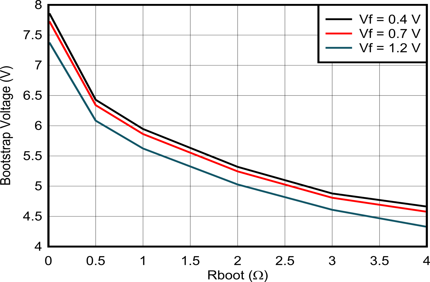
 Figure 4-1 Plot Showing Steady-state
Bootstrap Voltage Over Rboot and Diodes With Different Forward Voltages
Figure 4-1 Plot Showing Steady-state
Bootstrap Voltage Over Rboot and Diodes With Different Forward VoltagesThe GaN FET used in this example was rated for 6 V maximum on the gate. An Rboot less than 1-Ω results in a gate voltage that exceeds the rating of the GaN FET. Adding a 2-Ω Rboot reduces overcharge to a more reasonable level, under 5.5 V. This bootstrap method is simple and effective but has some drawbacks.
Rboot and Cboot form an RC filter. The start-up time of the system is determined by the time constant of the RC filter. Increasing Rboot increases the start-up time of the system. The amount of overcharging varies over load and temperature, therefore, designing Rboot to account for the worst-case operating point is essential. To account for the worst-case, Rboot must be larger and the start-up time increases further. Alternatively, adding inductance to the bootstrap circuit limits the bootstrap current. This relationship between inductance and current is given in Equation 4:
A correctly-sized inductor limits current buildup in the short dead time without impacting normal charging. Adding inductance returns slightly higher efficiency than resistance because the process recycles some energy instead of dissipating energy. One downside is that forcing the inductor current off when HS rises generates an inductive voltage spike. In addition to the oscillating current seen on Iboot in Figure 4-2, there is a corresponding voltage spike across the bootstrap diode.
 Figure 4-2 Waveform Comparing Iboot
Current With a 2-Ω Resistor, 4-Ω Resistor, and 22.5nH Inductor
Figure 4-2 Waveform Comparing Iboot
Current With a 2-Ω Resistor, 4-Ω Resistor, and 22.5nH InductorThe potential for an inductive voltage spike requires the bootstrap diode to include a higher blocking voltage and a smaller capacitance to reduce the ringing during reverse recovery. This over sizing, combined with the higher cost of inductors versus resistors, yields a costlier option than other methods.