SNVAAA6 September 2024 LM61495
4.4 Efficiency and Thermal Considerations
As described in previous sections so far, the power loss of IBB converter can be greater than the standard buck converter due to larger voltage and current stresses. This means that the efficiency of the IBB can be less than that of a buck under similar conditions. Estimating the efficiency before the IBB is designed and tested is not easy. Therefore, the best plan is to take a conservative approach to calculating the maximum operating currents when choosing a buck converter.
The increased power dissipation compared to the standard buck converter also has consequences for increasing die temperature. Every regulator has a maximum rated die temperature that must not be exceeded. Since the IBB has more dissipation than the equivalent buck, the extra heat needs to be removed or the die temperature can get too high. This means that the total θJA of the application can have to be lowered.
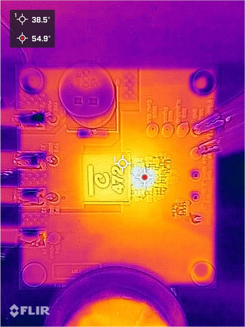
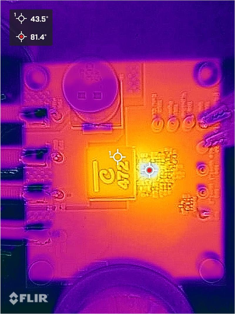
The maximum allowed IC junction temperature is 150°C as stated in the LM61495 data sheet. To calculate the IC temperature for different conditions, multiply the power loss of the LM61495 device by the θJA of PMP23333 PCB, and add this value to the ambient temperature. Since PMP23333 does not specify the θJA of PCB, we can estimate the θJA by checking actual efficiency and thermal results. Figure 4-11 and Figure 4-12 show the thermal results under - 2.7A, - 4A conditions when VIN = 12V, VOUT = -8V. Even though higher load can be used like described in Section 4.2 Texas Instruments does not recommend to increase the load more than – 4A in PMP23333 design since IC temperature can get to be too high.
 Figure 4-11 Thermal Result When
IOUT = - 2.7A
 Figure 4-12 Thermal Result When
IOUT = - 4A