SNVS358R July 2005 – June 2016 LP5900
PRODUCTION DATA.
8 Application and Implementation
NOTE
Information in the following applications sections is not part of the TI component specification, and TI does not warrant its accuracy or completeness. TI’s customers are responsible for determining suitability of components for their purposes. Customers should validate and test their design implementation to confirm system functionality.
8.1 Application Information
The LP5900 is a linear regulator capable of supplying a 150-mA output current. Designed to meet the requirements of RF and nalog circuits, the device provides low noise, high PSRR, low quiescent current, and low line transient response figures. Using new innovative design techniques the LP5900 offers class-leading device noise performance and is designed to work with 0.47-μF input and output ceramic capacitors (no bypass capacitor is required).
8.2 Typical Application
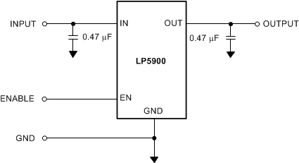
Figure 16 shows the typical application circuit for the LP5900. Input and output capacitances may need to be increased above the 0.47-μF minimum for some applications.
 Figure 16. LP5900 Typical Application
8.2.1 Design Requirements
| DESIGN PARAMETER | MIN | MAX | UNITS |
|---|---|---|---|
| Input voltage range | 2.5 | 5.5 | V |
| Output voltage | 2.8 | V | |
| Output current | 150 | mA | |
| Output capacitor range | 0.47 | 10 | μF |
| Input/Output capacitor ESR range | 5 | 500 | mΩ |
8.2.2 Detailed Design Procedure
8.2.2.1 Power Dissipation
The permissible power dissipation for any package is a measure of the capability of the device to pass heat from the power source, the junctions of the device, to the ultimate heat sink, the ambient environment. Thus the power dissipation is dependent on the ambient temperature and the thermal resistance across the various interfaces between the die and ambient air. As stated in Recommended Operating Conditions, the allowable power dissipation for the device in a given package can be calculated using Equation 1:

The actual power dissipation across the device can be represented by Equation 2:
This establishes the relationship between the power dissipation allowed due to thermal consideration, the voltage drop across the device, and the continuous current capability of the device. These two equations should be used to determine the optimum operating conditions for the device in the application.
8.2.2.2 External Capacitors
Like any low-dropout regulator, the LP5900 requires external capacitors for regulator stability. The LP5900 is specifically designed for portable applications requiring minimum board space and smallest components. These capacitors must be correctly selected for good performance.
8.2.2.2.1 Input Capacitor
An input capacitor is required for stability. The input capacitor should be at least equal to or greater than the output capacitor. It is recommended that a 0.47-µF capacitor be connected between the LP5900 IN pin and ground.
This capacitor must be located a distance of not more than 1 cm from the input pin and returned to a clean analog ground. Any good quality ceramic, tantalum, or film capacitor may be used at the input.
Important: To ensure stable operation it is essential that good PCB practices are employed to minimize ground impedance and keep input inductance low. If these conditions cannot be met, or if long leads are to be used to connect the battery or other power source to the LP5900, then it is recommended to increase the input capacitor to at least 2.2 µF. Also, tantalum capacitors can suffer catastrophic failures due to surge current when connected to a low-impedance source of power (like a battery or a very large capacitor). If a tantalum capacitor is used at the input, it must be ensured by the manufacturer to have a surge current rating sufficient for the application. There are no requirements for the equivalent series resistance (ESR) on the input capacitor, but tolerance and temperature coefficient must be considered when selecting the capacitor to ensure the capacitance will remain 0.47 μF ±30% over the entire operating temperature range.
8.2.2.2.2 Output Capacitor
The LP5900 is designed specifically to work with very small ceramic output capacitors. A ceramic capacitor (dielectric types X5R or X7R) in the 0.47 μF to 10 μF range, and with ESR between 5 mΩ to 500 mΩ, is suitable in the LP5900 application circuit. For this device the output capacitor should be connected between the OUT pin and a good ground connection and should be mounted within 1 cm of the device.
It may also be possible to use tantalum or film capacitors at the device output, OUT, but these are not as attractive for reasons of size and cost (see the Capacitor Characteristics section below).
The output capacitor must meet the requirement for the minimum value of capacitance and have an ESR value that is within the range 5 mΩ to 500 mΩ for stability.
8.2.2.2.3 Capacitor Characteristics
The LP5900 is designed to work with ceramic capacitors on the input and output to take advantage of the benefits they offer. For capacitance values in the range of 0.47 μF to 4.7 μF, ceramic capacitors are the smallest, least expensive and have the lowest ESR values, thus making them best for eliminating high frequency noise. The ESR of a typical 0.47-μF ceramic capacitor is in the range of 20 mΩ to 40 mΩ, which easily meets the equivalent series resistance (ESR) requirement for stability for the LP5900.
The temperature performance of ceramic capacitors varies by type and manufacturer. Most large value ceramic capacitors (≥ 2.2 µF) are manufactured with Z5U or Y5V temperature characteristics, which results in the capacitance dropping by more than 50% as the temperature goes from 25°C to 85°C.
A better choice for temperature coefficient in a ceramic capacitor is X7R. This type of capacitor is the most stable and holds the capacitance within ±15% over the temperature range. Tantalum capacitors are less desirable than ceramic for use as output capacitors because they are more expensive when comparing equivalent capacitance and voltage ratings in the 0.47 μF to 4.7 μF range.
Another important consideration is that tantalum capacitors have higher ESR values than equivalent size ceramics. This means that while it may be possible to find a tantalum capacitor with an ESR value within the stable range, it would have to be larger in capacitance (which means bigger and more costly) than a ceramic capacitor with the same ESR value. It should also be noted that the ESR of a typical tantalum will increase about 2:1 as the temperature goes from 25°C down to −40°C, so some guard band must be allowed.
8.2.3 Application Curve
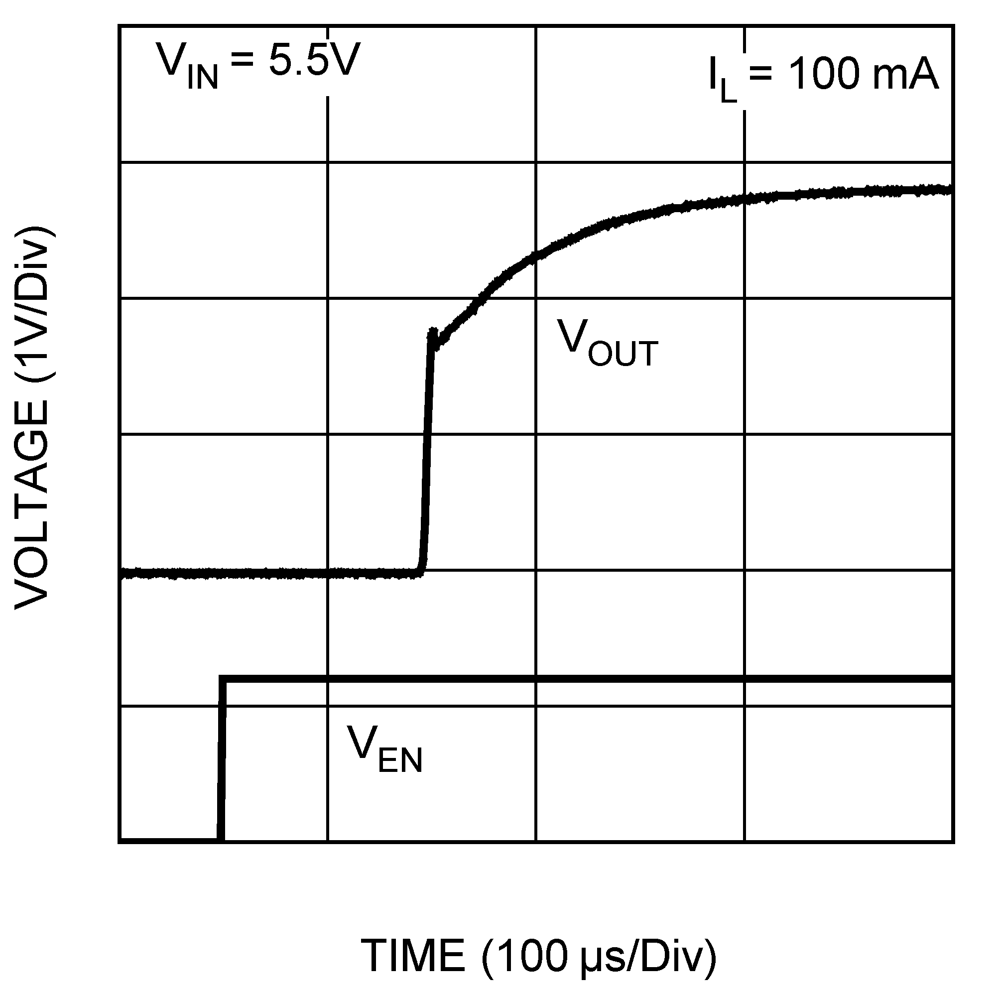
 Figure 17. Enable Start-up Time, IOUT = 100 mA, VOUT = 2.8 V