SNVT013 January 2024 LMQ66430 , LMQ66430-Q1 , LMR66430 , LMR66430-Q1
Introduction
A step-down converter pulses on the totem-pole, power, and field-effect transistors (FETs) to generate a pulse-width modulation (PWM) signal (Figure 1-1). The PWM signal is filtered to produce the output voltage (VOUT). The input capacitors (CIN) support the AC current required during the high-side FETs on-time, D. These AC waveforms create a hurdle in passing noise-compliance standards, such as CISPR 25 Class 5.
 Figure 1 Step-Down Converter Schematic
and Waveforms
Figure 1 Step-Down Converter Schematic
and WaveformsStep-Down Conversion Noise Concerns
High-ambient, step-down converter operation is achieved with low power dissipation. FET power dissipation is minimized by rapid switching. The input current has high energy harmonics as a consequence of the rapid switching. The 2.2MHz operation is then often challenging when more stringent noise standards need to be met.
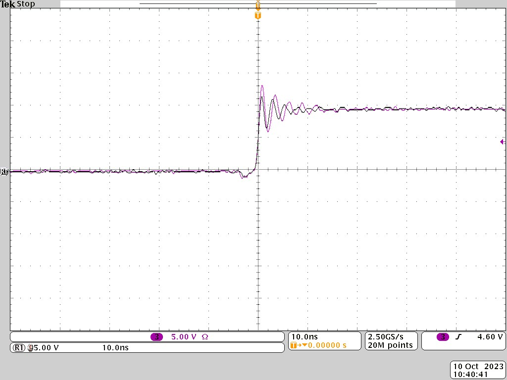
The FET rapid turn-on, turn-off leads to an inductive ring which is seen in the switch waveform (Figure 1-2). Converter data sheets show that input capacitors must be close to VIN and GND pins. This makes sure that the input loop inductance is low enough to reduce the inductive ring amplitude.
Figure 1-2 demonstrates the switch node ring. The reference trace (grey)
has the input capacitor placed 70 mils closer to the VIN pin of the
device, in comparison to the overlaid purple trace. This results in approximately
a
3 Vp-p ring amplitude increase, impacting
radiated noise which often includes this frequency range.
 Figure 2 Switch-Node Ring With
Different Capacitor Placement
Figure 2 Switch-Node Ring With
Different Capacitor PlacementCapacitor Integration for Noise Reduction
LMQ66430-Q1 takes noise reduction a step further. This device implements integrated (VIN) capacitors directly on the device lead frame, fully encapsulated. This reduces the input loop inductance and the area. The reduced loop inductance and area impacts the magnetically coupled, broadband (harmonic) noise. These are directly proportional, so noise generation is reduced. LMR66430-Q1 is the non-integrated-capacitor version of LMQ66430-Q1. Figure 1-3 highlights the difference in conducted noise, with a sweep from 30MHz to 108MHz. Additionally, Figure 1-4, Figure 1-5, and Figure 1-6 demonstrate the difference in radiated noise. These sweeps were conducted on an identical PCB, under the same power conditions, and setup.
 Figure 3 Conducted CISPR 25 Class 5
Sweep (30MHz to 108MHz)
 Figure 4 Radiated CISPR 25 Class 5
Sweep (Rod Antenna: 150kHz to 28MHz)
 Figure 5 Radiated CISPR 25 Class 5
Sweep (Biconical Antenna: 30MHz to 230MHz)
 Figure 6 Radiated CISPR 25 Class 5
Sweep (Log Periodic Antenna: 300MHz to 960MHz)
Figure 6 Radiated CISPR 25 Class 5
Sweep (Log Periodic Antenna: 300MHz to 960MHz)Input Capacitor Design for Automotive Reliability
Input capacitors are often a multilayer, ceramic chip capacitor (MLCC). Over time, these capacitors can fail due to shock (that is, vibration, temperature, or mechanical). Standard MLCCs tend to fail-short, which can lead to system thermal instance.
LMQ66430-Q1 has integrated MLCC, input capacitors causing the same concerns for designers. This device utilizes 0201, AEC-Q200, integrated capacitors. The two VIN capacitors are placed in series between pin 3 and pin 6 (Figure 1-7). Having two capacitors in series reduces the risk of a fail-short to ground, because both capacitors have to fail. Additionally, having the capacitors orientated in a L-shape arrangement, reduces overall stress. Lifetime stress is reduced as stress is greatest when applied on the same axis. Lastly, the integrated, 0201 capacitors are a soft-termination type. Soft-termination, MLCCs are less prone to cracking. The LMQ64430-Q1 capacitor integration technique leads to a respectable temperature cycle report as shown in Table 1.
 Figure 7 LMQ66430-Q1 Capacitor
Integration
Figure 7 LMQ66430-Q1 Capacitor
Integration| LMQ66430-Q1 Temperature Cycling Results | |
|---|---|
| Test Standard | IPC-9701 |
| # of passing cycles | > 6080 (without failure, in-progress) |
Conclusion
Automotive noise requirements are becoming more concerning in designs. Capacitor integration is important for low noise, reducing noise with loop inductance reduction and area reduction. This provides simple layout and design for achieving CISPR 25 Class 5 compliance. Automotive safety also remains a concern for designers. Having an input capacitor short the battery terminals together can lead to a thermal instance. Designers are considering capacitor selection, placement, and series-use to reduce thermal instance probability. LMQ66430-Q1 or LMR66430-Q1 can be considered for low-noise, safety-critical designs as these devices are intended to achieve these typical, automotive, step-down requirements more easily.
References
- Texas Instruments, LMQ664x0-Q1, 36-V, 1-A, 2-A, and 3-A, Ultra-Small, Synchronous Automotive Step-Down Converter with Integrated VIN Bypass and CBOOT Capacitors Data Sheet
- Texas Instruments, LMR664x0-Q1, 36-V, 1-A, 2-A, and 3-A, Ultra-Small, Synchronous, Automotive Step-Down Converter Data Sheet
- Texas Instruments, LMQ66430-Q1 Buck Controller Evaluation Module User’s Guide
- Texas Instruments, LMR66430-Q1 Evaluation Module User’s Guide
- Texas Instruments, Reduce buck-converter EMI and voltage stress by minimizing inductive parasitics analog applications journal