SNVU621D May 2019 – July 2021 LM61440 , LM61440-Q1 , LM61460 , LM61460-Q1
2 Quick Start
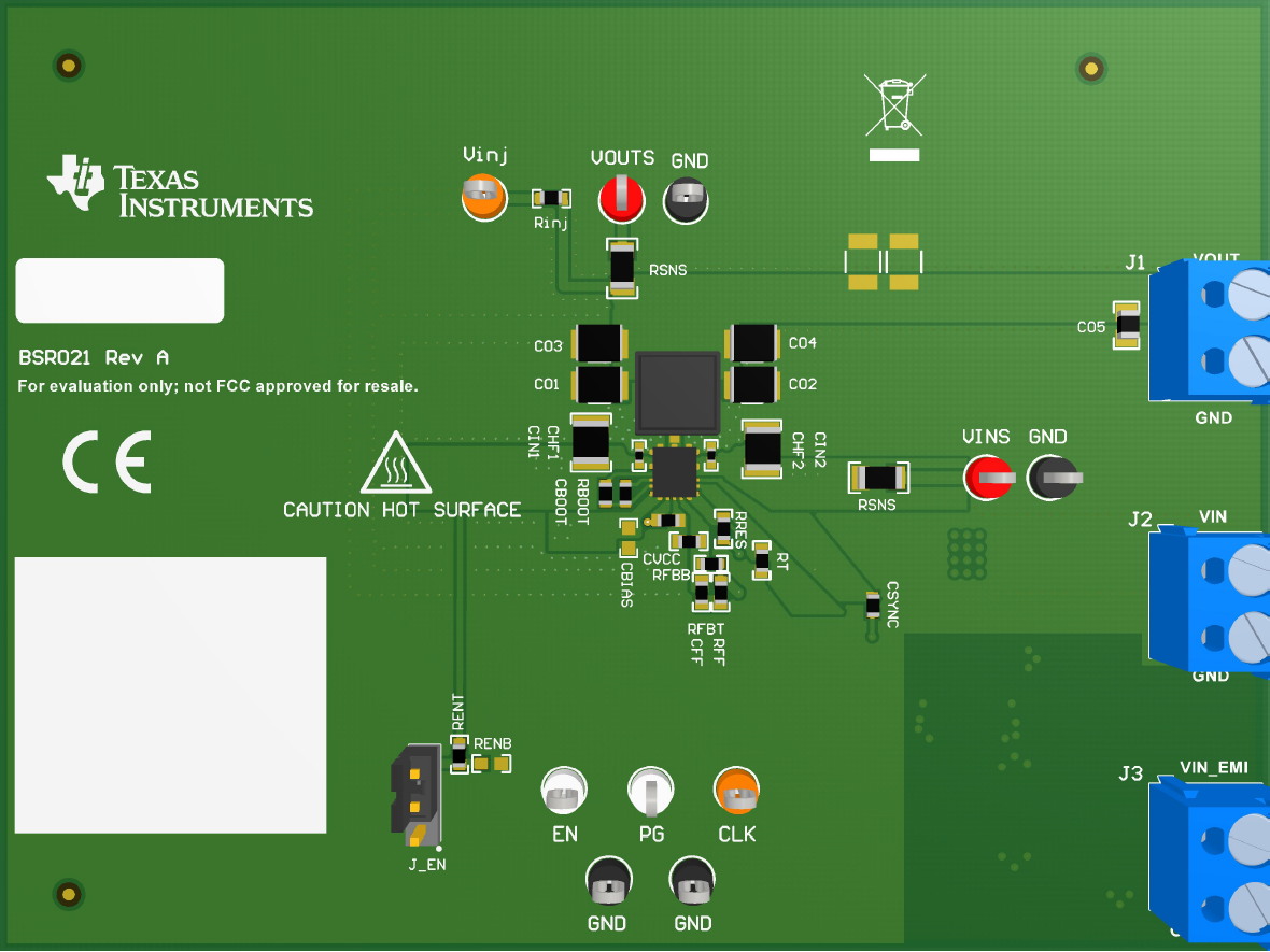
- Connect the voltage supply between the VIN and GND connectors or between VIN_EMI and GND_EMI to include the on-board input filter in the input path. Use short and thick gauge wires to minimize inductance and IR drop. Note that sense points for VIN and VOUT are provided.
- Connect the load of the converter between VOUT and GND connectors using short and thick wires.
- Set the supply voltage at an appropriate level between 6 V to 36 V. The 6 V minimum ensures enough head room for VOUT to equal 5 V at a 6 A load current. Set the current limit of the supply to an appropriate level to supply needed current and protection.
- Turn on the power supply. With the default configuration, the EVM powers up and provides VOUT = 5 V.
- Monitor the output voltage with sense points. The maximum load current must be 6 A with the LM61460-Q1. Note that the maximum output current may need to derate if ambient temperature is high, especially if device is operated at higher frequency, for example, 2.2MHz.
See Figure 2-1 for connector locations.
 Figure 2-1 Top View
of LM61460-Q1 EVM