SNVU735 September 2020 LV14360
2.1 Input/Output Connector Description
VIN — Terminal TP1 – The power input terminal for the converter. Adjacent to it is the GND reference ground. Use this terminal to attach the EVM to a cable harness.
VOUT — Terminal TP3 – The regulated output voltage for the converter. Adjacent to it is the GND reference ground.
GND — Terminal TP2, TP4 – The ground reference for the converter. Use these terminals to attach the EVM to a cable harness.
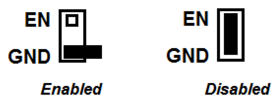
EN — Jumper J1 – Used to enable the switch-mode converter. The device will be enabled when the respective jumper is high or floating, and disabled when low. EN turnon trip point also can be programmed by changing R1 or R2. Refer to LV14360 data sheet for enable and adjustable undervoltage lockout.
 Figure 2-1 Enable Jumper Setting
SYNC — Jumper J2 – Used to synchronize the switching frequency to external clock. Refer to data sheet for detailed application information.
PGOOD — Jumper J4 – Used to monitor the Power-Good flag. This flag indicates whether the output voltage has reached its regulation point. The U1 PGOOD pin is an open-drain output that requires a pullup resistor to the appropriate logic voltage (any voltage less than 7 V). A pre-installed resistor R4 of 10.2 kΩ is tied to the PGOOD pin and R9 of 49.9 Ω brought output to J4 PULLUP pin.
Test point — TP6, TP7, TP8 – Test points used for loop response measurements