SNVU758 February 2021 TPSM13604H
1 Getting Started
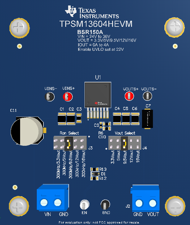
Figure 1-1 details the user interface items associated with the EVM. The VIN terminal block (J1) is used for connection to the host input supply and the VOUT terminal block (J2) is used for connection to the load. These terminal blocks accept up to 14-AWG wire.
 Figure 1-1 EVM User
Interface
Figure 1-1 EVM User
Interface- Use the VIN S+ and VIN S- test points along with the VOUT S+ and VOUT S- test points located near the power terminal blocks as voltage monitoring points where voltmeters can be connected to measure VIN and VOUT. Do not use these S+ and S- monitoring test points as the input supply or output load connection points. The PCB traces connecting to these test points are not designed to support high currents.
- The control test points located near the bottom of the EVM test the features of the device. For more information on the individual control test points, see Section 2.
- The Ron Select jumper (J3) is provided to set the switching frequency according to the set output voltage. To set the switching frequency to a different value, change the appropriate Ron resistor according to the device-specific data sheet equation.
- The Vout Select jumper (J4) is provided to select the desired output voltage: 3.3-V, 5-V, 9.5-V, 12-V, and 16-V. Before applying power to the EVM, make sure that the jumper is present and properly positioned for the intended output voltage. Always remove input power before changing the jumper settings.
- The device is configured to turn on with an under-voltage lockout (UVLO) of 22-V. The UVLO can be modified to a different desired voltage by changing the R13 resistor on the EVM.