SNVU836A March   2023  – April 2024 LP5891-Q1


  1.   1
  2.   Description
  3.   Features
  4.   Applications
  5.   5
  6. 1Evaluation Module Overview
    1. 1.1 Introduction
    2. 1.2 Kit Contents
    3. 1.3 Specification
    4. 1.4 Device Information
  7. 2Hardware
    1. 2.1 Function Descriptions
    2. 2.2 Test Setup
      1. 2.2.1 System/Tool Requirements
      2. 2.2.2 Hardware Setup for Single Device
      3. 2.2.3 Hardware Setup for Dual Cascaded Devices
  8. 3Software
    1. 3.1 Software Setup
  9. 4Hardware Design Files
    1. 4.1 Schematic
    2. 4.2 PCB Layout
    3. 4.3 Bill of Materials
  10. 5Additional Information
    1. 5.1 Additional Resources
    2. 5.2 Trademarks
  11. 6Revision History

PCB Layout

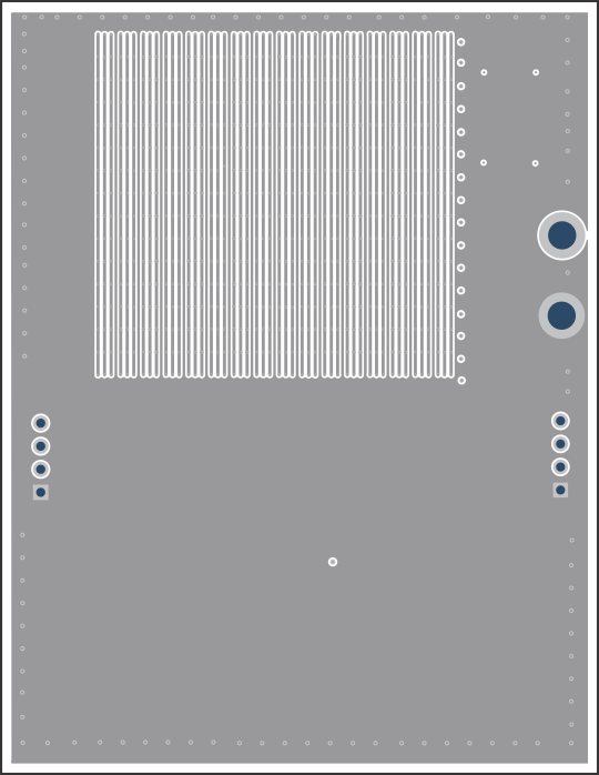
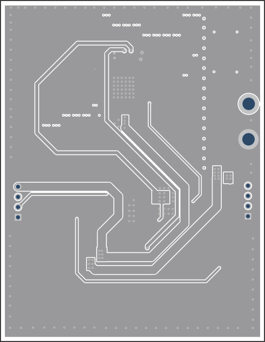
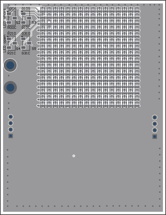
The PCB layout of the EVM is shown below.
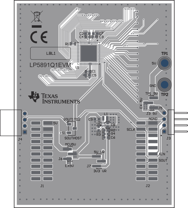
GUID-20220906-SS0I-GLZT-VFHK-QSGDVJJF1RDG-low.gifFigure 4-5 LP5891Q1EVM Top Layer
GUID-20220906-SS0I-FLQ4-WJX2-PZJKJTPPDF5H-low.gifFigure 4-7 LP5891Q1EVM Signal Layer 2
GUID-20220906-SS0I-HLCT-GMJX-ZPQGDN2ZMZCT-low.gifFigure 4-6 LP5891Q1EVM Signal Layer 1
GUID-20220906-SS0I-K0HZ-TQ0M-VHZQ22PRRH6G-low.gifFigure 4-8 LP5891Q1EVM Bottom Layer