SNVU836A March 2023 – April 2024 LP5891-Q1
2.1 Function Descriptions
This section describes the connectors, jumpers, and switches on the LP5891Q1EVM board.
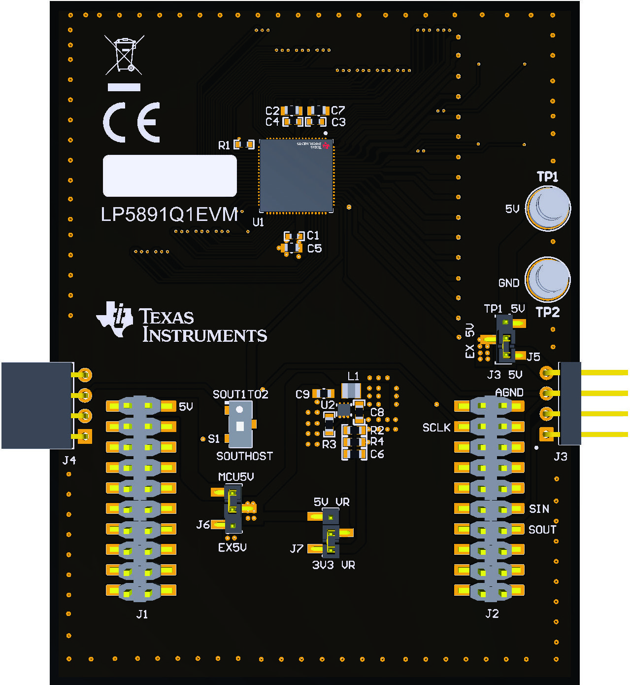
Figure 3-1 shows the image of the driver IC side of the LP5891Q1EVM board.
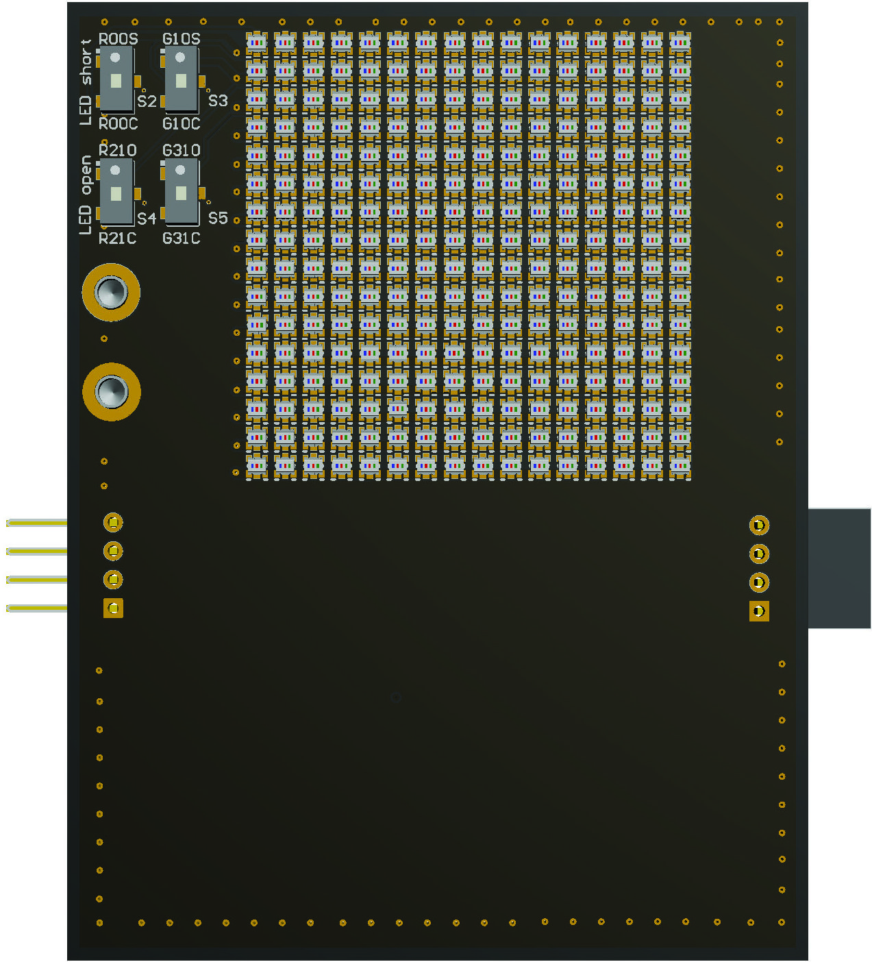
Figure 3-2 shows the image of the LED side of the LP5891Q1EVM board.
 Figure 2-1 Driver IC Side of the LP5891Q1EVM
Board
 Figure 2-2 LED Side of the LP5891Q1EVM
Board
Figure 2-2 LED Side of the LP5891Q1EVM
BoardThe LP5891Q1EVM works with a host controller, the TMS320F280039C LaunchPad™ for C2000™ real-time MCU. The LP5891Q1EVM is designed with connectors, jumpers, and switches to support device-to-device connection, device-to-host connection, and flexible power supply scheme. In addition, there are four switches on the LED side of the LP5891Q1EVM board that enables the evaluation of LED open and short detection and removal functions of the LP5891-Q1.
Table 3-1 lists the connectors of LP5891Q1EVM board and the descriptions.
Table 3-2 lists the jumpers of LP5891Q1EVM board and the descriptions.
Table 3-2 lists the switches of LP5891Q1EVM board and the descriptions.
| Name | Description |
|---|---|
| J1, J2 | Boosterpack connectors for connecting with the TMS320F280039C LaunchPad. |
|
J3 |
Input board-to-board connectors between LP5891Q1EVM boards, including +5V, SIN (serial data input), SCLK (serial clock), and GND. |
|
J4 |
Output board-to-board connectors between LP5891Q1EVM boards, including +5V, SOUT (serial data output), SCLK (serial clock), and GND. |
|
TP1 (+5V) |
External power supply that can be selected for VLEDG/VLEDB and DC/DC. |
| TP2 (GND) | Supply ground. |
| Name | Description |
|---|---|
|
J3 |
J3 is used to
select external +5V power supply.
|
|
J6 |
J3 is used to
select the +5V power supply that supplies VLEDG/VLEDB and DC/DC.
|
|
J7 |
J7 is used to
select the power supply that supplies VLEDR.
|
| Name | Description |
|---|---|
|
S1 |
|
|
S2 |
|
|
S3 |
|
|
S4 |
|
|
S5 |
|