SNVU848 November 2023 LMR38025-Q1
7 Performance Curves
Figure 7-1 through Figure 7-9 present the typical performance of the LMR38025QEVM according to the configuration described in Section 2. Based on measurement techniques and environmental variables measurements can differ slightly than the data presented.
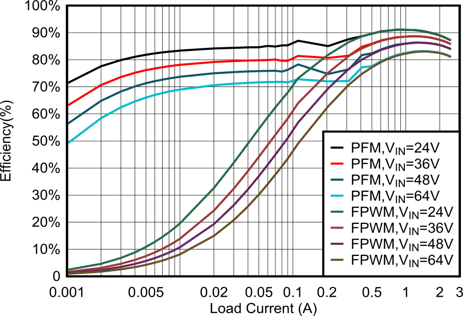 Figure 7-1 Efficiency vs Load
Current
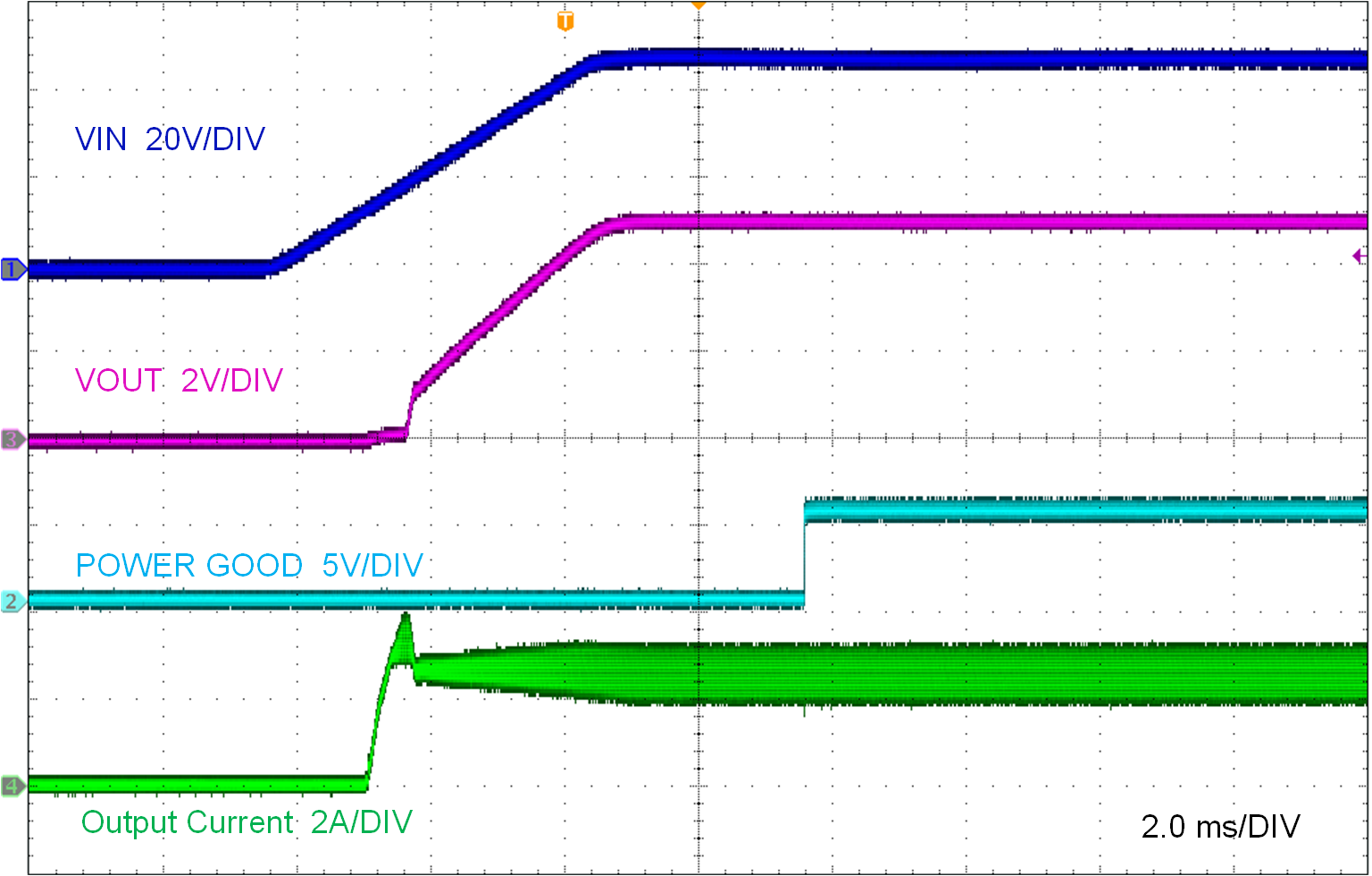 Figure 7-3 Start-Up: VIN =
48 V, VOUT = 5 V, IOUT = 2.5 A
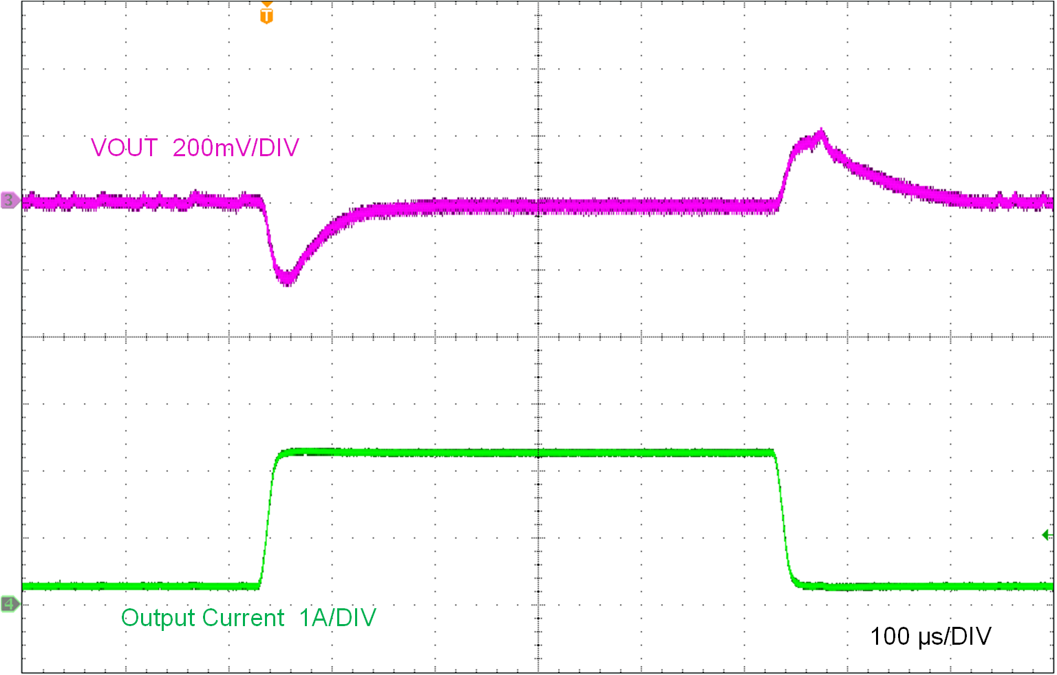 Figure 7-5 Load Transient:
VIN = 48 V, VOUT = 5 V, IOUT= 250 mA to
2.25 A at 200 mA/µs
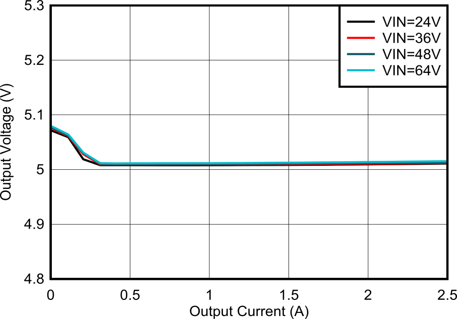 Figure 7-2 Load Regulation
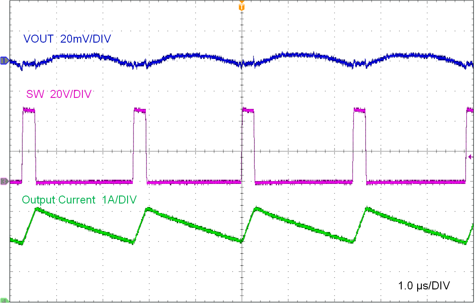 Figure 7-4 Full Load Switching:
VIN = 48 V, VOUT = 5 V, IOUT = 2.5
A
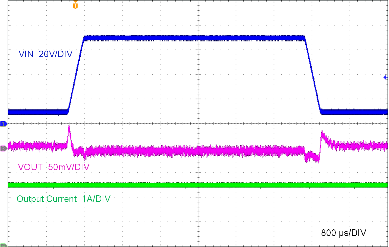 Figure 7-6 Line Transient:
VIN = 10 V to 70 V at 200 V/ms, VOUT = 5 V,
IOUT = 2.5 A
 Figure 7-7 Control
Loop Response: VIN = 48 V, VOUT = 5 V,
IOUT = 2.5 A
 |
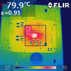 Figure 7-8 Thermal
Capture of EVM: VIN = 48 V, VOUT = 5
V, IOUT = 2.5 A
 |
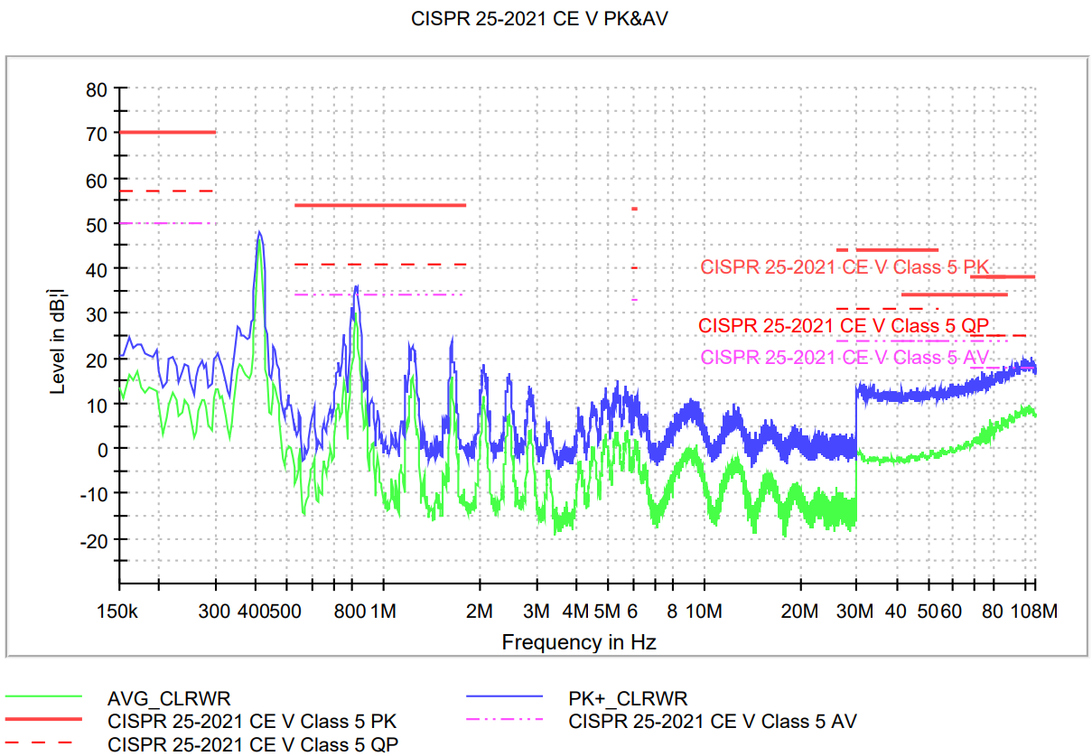 Figure 7-9 CISPR 25
Class 5 Conducted Emissions Plot: VIN = 48 V,
VOUT = 5 V, IOUT = 2.5 A
 |