SNVU890 January 2024
3.1.2 Performance Data and Results
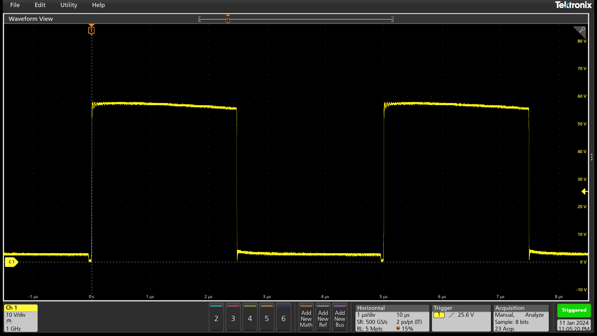
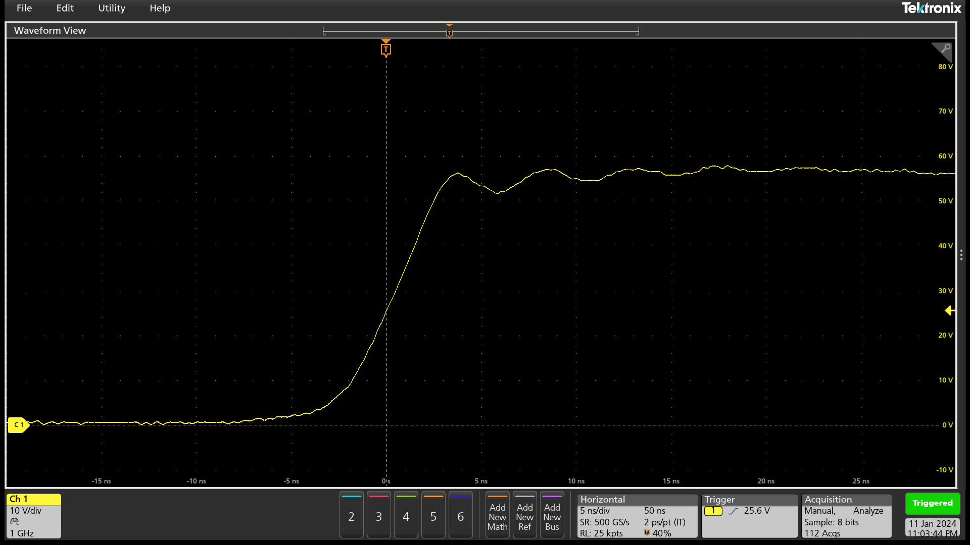
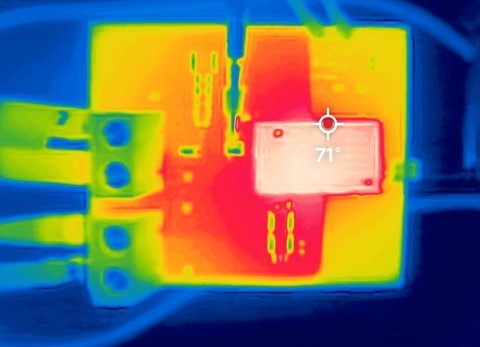
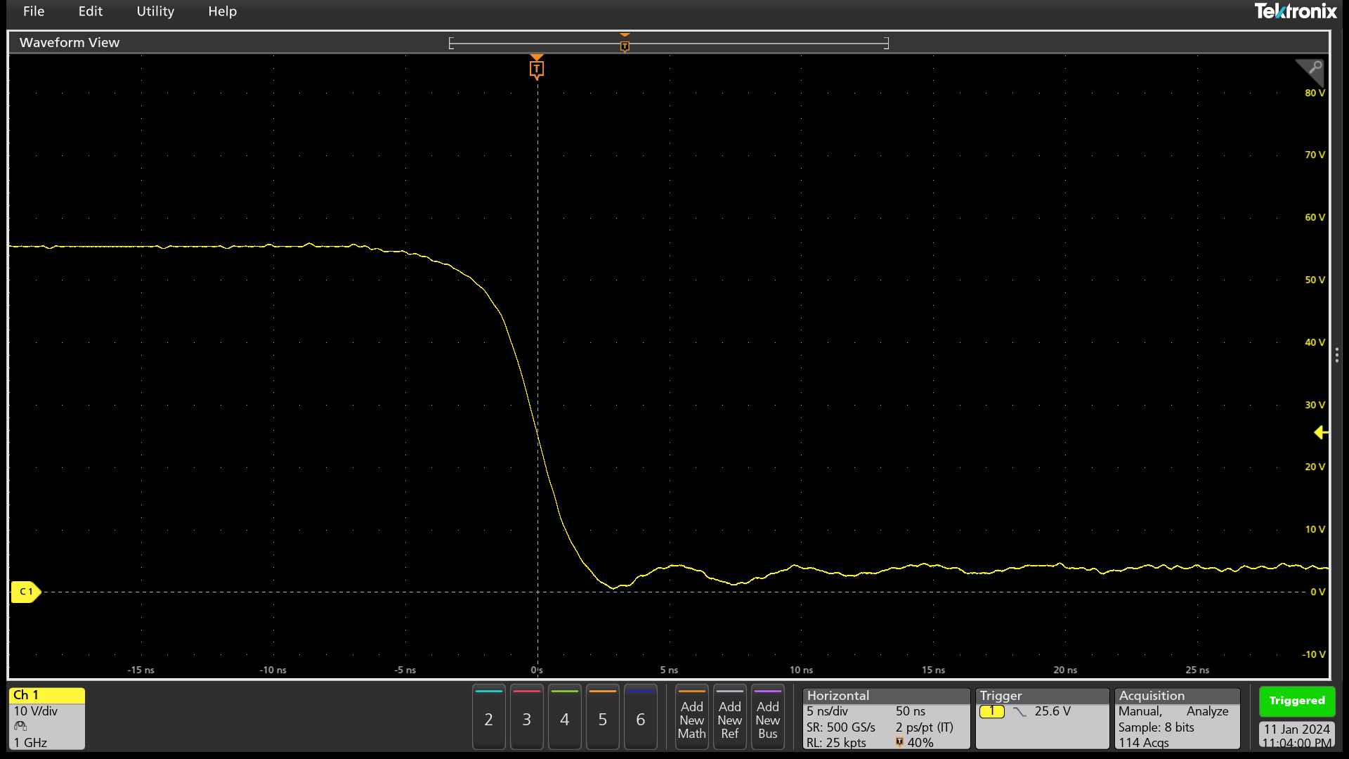
The following waveforms and thermal image are collected from a buck converter test setup with the following conditions: Vin: 60V, Fsw: 200kHz, Duty Cycle: 50%, Iout: 20A, Tamb: 23C, with heat sink no airflow
 Figure 3-3 SW Node Full Switching
Period
 Figure 3-5 SW
Node Low-Side Turn-Off
 Figure 3-4 Thermal Capture of EVM After Steady State
 Figure 3-6 SW Node Low-Side
Turn-On
Figure 3-6 SW Node Low-Side
Turn-OnNote: Visit the E2E forum Gallium Nitride Solutions
for more information regarding LMG3100 or LMG3100 hard-switched
EVM.