-
Using USB Host Mode on the EK-TM4C123GXL LaunchPad SPNA243 June 2020 TM4C1236D5PM , TM4C1236D5PM , TM4C1236E6PM , TM4C1236E6PM , TM4C1236H6PM , TM4C1236H6PM , TM4C1237D5PM , TM4C1237D5PM , TM4C1237D5PZ , TM4C1237D5PZ , TM4C1237E6PM , TM4C1237E6PM , TM4C1237E6PZ , TM4C1237E6PZ , TM4C1237H6PGE , TM4C1237H6PGE , TM4C1237H6PM , TM4C1237H6PM , TM4C1237H6PZ , TM4C1237H6PZ , TM4C123FE6PM , TM4C123FE6PM , TM4C123FH6PM , TM4C123FH6PM , TM4C123GE6PM , TM4C123GE6PM , TM4C123GE6PZ , TM4C123GE6PZ , TM4C123GH6PGE , TM4C123GH6PGE , TM4C123GH6PM , TM4C123GH6PM , TM4C123GH6PZ , TM4C123GH6PZ , TM4C123GH6ZRB , TM4C123GH6ZRB , TM4C123GH6ZXR , TM4C123GH6ZXR
-
Using USB Host Mode on the EK-TM4C123GXL LaunchPad
- Using USB Host Mode on the EK-TM4C123GXL LaunchPad
- IMPORTANT NOTICE
Using USB Host Mode on the EK-TM4C123GXL LaunchPad
Using USB Host Mode on the EK-TM4C123GXL LaunchPad
The EK-TM4C123GXL LaunchPad™ Evaluation Kit is a low-cost evaluation platform for Arm®Cortex®-M4F based microcontrollers from Texas Instruments. The design of the TM4C123G LaunchPad highlights the TM4C123GH6PM microcontroller (MCU) with a USB 2.0 device interface and features including hibernation, user buttons and an RGB LED for custom applications. This application report demonstrates how to turn the LaunchPad into both a USB host and USB device capable evaluation kit for USB application developments. Along with the application report are four USB host examples that interface with a USB mouse, keyboard or USB memory stick.
Project collateral and source code discussed in this application can be downloaded from the following URL: http://www.ti.com/lit/zip/spna243.
Trademarks
LaunchPad, Code Composer Studio are registered trademarks of Texas Instruments.
Arm, Cortex are registered trademarks of Arm Limited (or its subsidiaries) in the US and/or elsewhere.
All other trademarks are the property of their respective owners.
1 EK-TM4C123GXL Board Overview
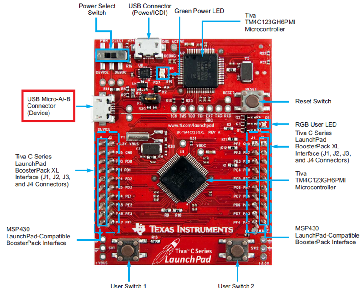
Figure 1 shows a photo of the EK-TM4C123GXL LaunchPad board. As can be seen, there are two USB connectors on the board. On the top side is the USB connector for the in-circuit debug interface (ICDI). On the left side is the second USB Micro-A/B connector. Although this micro-A/B connector is capable for USB device, host and on-the-go (OTG) connectivity, the board as is can only support USB device connectivity. In other words, the EK-TM4C123GXL is only designed to function as a USB device without hardware modification. The lack of USBID and USBVBUS signals at the connector are preventing the board from functioning as a USB host or USB OTG. The USBVBUS signal is required during the session request protocol and it allows the USB PHY to both sense the voltage level of VBUS and pull up VBUS momentarily during the VBUS pulsing. The VBUSID is used by the USB PHY to determine the initial state of the USB controller (pulled down is the A side of the cable and pulled up is the B side).
 Figure 1. Arm Cortex-M4F Based MCU TM4C123G LaunchPad Evaluation Kit
 2 Board Modification to Make EK-TM4C123GXL USB Host/OTG Capable
The TM4C123GH6PM MCU is capable of USB embedded host and OTG functions. The OTG functionality can be enabled by populating R25 and R29 with 0-Ω resistors. These resistors connect the USB ID and USB VBUS signals on the USB device connector to the PB0 and PB1 pins on the MCU. When these resistors are populated, the PB0 and PB1 pins must remain in their respective USB pin mode configurations to prevent device damage. The PB0 and PB1 pins are also present on the J1 BootsterPack header. Therefore, if R25 or R29 are populated, care must be taken not to conflict these signals with BoosterPack signals. For R25 and R29 locations on the board, see Figure 2.
 Figure 2. EK-TM4C123GXL LaunchPad R25 and R29 Resistors Location
 The Tiva C Series LaunchPad can be powered from one of the two power sources:
- On-board ICDI USB cable (Debug, Default)
- USB device cable (Device)
The POWER SELECT switch (SW3) is used to select one of the two power sources. When the LaunchPad functions as a USB device, it can receive power from the external USB host by toggling the SW3 switch.
For the power selection schematic, see Figure 3.
 Figure 3. EK-TM4C123GXL LaunchPad Power Selection Schematic
 However, in order for the LaunchPad to function as a USB host when the USB device requires bus power, it needs to supply a 5 V power source to the USB device. As a result of the current Power Select switch design, the USB VBUS pin on the Device USB connector (+USB_VBUS) is not connected to the USB VBUS input on the Debug USB connector (+ICDI_VBUS). Therefore, the Device USB connector cannot provide 5 V to any USB device that requires bus power without a hardware modification.
The required hardware modification needs to route the USB VBUS from the Debug USB connector to the Device USB connector. This can be done by connecting the H18 and H19 test points shown in Figure 3 together so the 5 V power from the Debug connector (+ICDI_VBUS) is routed to the Device connector (+USB_VBUS). H18 and H19 are unmarked on the LaunchPad.
Figure 4 shows shows these tied together using a jumper wire.
 Figure 4. EK-TM4C123GXL LaunchPad H18 and H19 Locations
 With the two board modifications, the EK-TM4C123GXL is now able to function as a USB device, USB host or OTG.