SPNA243 June 2020 TM4C1236D5PM , TM4C1236D5PM , TM4C1236E6PM , TM4C1236E6PM , TM4C1236H6PM , TM4C1236H6PM , TM4C1237D5PM , TM4C1237D5PM , TM4C1237D5PZ , TM4C1237D5PZ , TM4C1237E6PM , TM4C1237E6PM , TM4C1237E6PZ , TM4C1237E6PZ , TM4C1237H6PGE , TM4C1237H6PGE , TM4C1237H6PM , TM4C1237H6PM , TM4C1237H6PZ , TM4C1237H6PZ , TM4C123FE6PM , TM4C123FE6PM , TM4C123FH6PM , TM4C123FH6PM , TM4C123GE6PM , TM4C123GE6PM , TM4C123GE6PZ , TM4C123GE6PZ , TM4C123GH6PGE , TM4C123GH6PGE , TM4C123GH6PM , TM4C123GH6PM , TM4C123GH6PZ , TM4C123GH6PZ , TM4C123GH6ZRB , TM4C123GH6ZRB , TM4C123GH6ZXR , TM4C123GH6ZXR
- Using USB Host Mode on the EK-TM4C123GXL LaunchPad
1 EK-TM4C123GXL Board Overview
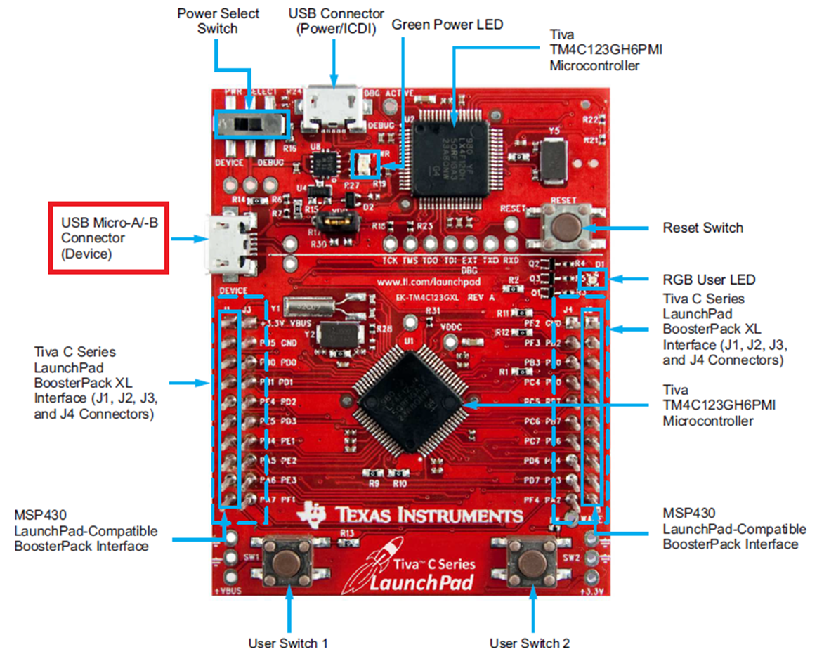
Figure 1 shows a photo of the EK-TM4C123GXL LaunchPad board. As can be seen, there are two USB connectors on the board. On the top side is the USB connector for the in-circuit debug interface (ICDI). On the left side is the second USB Micro-A/B connector. Although this micro-A/B connector is capable for USB device, host and on-the-go (OTG) connectivity, the board as is can only support USB device connectivity. In other words, the EK-TM4C123GXL is only designed to function as a USB device without hardware modification. The lack of USBID and USBVBUS signals at the connector are preventing the board from functioning as a USB host or USB OTG. The USBVBUS signal is required during the session request protocol and it allows the USB PHY to both sense the voltage level of VBUS and pull up VBUS momentarily during the VBUS pulsing. The VBUSID is used by the USB PHY to determine the initial state of the USB controller (pulled down is the A side of the cable and pulled up is the B side).
 Figure 1. Arm Cortex-M4F Based MCU TM4C123G LaunchPad Evaluation Kit