SPNK004 March 2024 TMS570LC4357-SEP
2 Total Dose Test Setup
Test Overview
The TMS570LC4357-SEP F021 is built with TI’s F021 CMOS process technology. Both HDR (biased) and LDR (unbiased) tests were performed, per MIL-STD-883, Test Method 1019.9, Condition A and B. The TMS570LC4357-SEP was irradiated up to 30krad(Si) and then put through complete electrical parametric testing on production Automated Test Equipment (ATE). Post irradiation, the devices were functional and passed all electrical parametric tests with readings within guard bands of the data sheet electrical specification limits.
Test Description and Facilities
The TMS570LC4357-SEP LDR exposure was performed on unbiased devices in a Co60 gamma cell under a 10 mrad(Si)/s exposure rate. The dose rate of the irradiator used in the exposure ranges from less than 10mrad(Si) / s to a maximum of approximately 65 rad(Si)/s is determined by the distance from the source. The exposure boards are housed in a lead-aluminum box (as specified in MIL-STD-883 TM 1019.9) to harden the gamma spectrum and minimize dose enhancement effects. The initial TMS570LC4357-SEP HDR exposure (three units) was performed on biased devices in a Co60 gamma cell at Aeroflex RADs, Colorado Springs, CO.: the unattenuated dose rate of this cell is 65 rad(Si)/s. After exposure, the devices were packed in dry ice (per MIL-STD-883 Method 1019.9 section 3.10) and returned to TI Dallas for a full post radiation electrical evaluation using Texas Instruments production Automated Test Equipment (ATE). Post radiation measurements were taken within 30 minutes of removal of the devices form the dry ice container. The devices were allowed to reach room temperature prior to electrical post radiation measurements. Follow-up HDR characterization on the ADC and FLASH content of TMS570LC4357-SEP was performed in Texas Instruments Dallas area lab (CLAB), also using a Co60 gamma cell with an unattenuated dose rate of 188rad(Si) / s. Total elapsed time from the end of the Gamma-cell exposure to test on ATE was approximately 45 minutes, with test at room temperature. ATE guard band test limits are set within data sheet electrical limits to meet a minimum Cpk and test error margin based on initial qualification and characterization data.
Test Setup Details
The LDR exposure was performed under unbiased conditions, and the HDR exposure was performed under biased conditions as described below:
For the unbiased LDR conditions, the exposure was performed with all pins grounded.
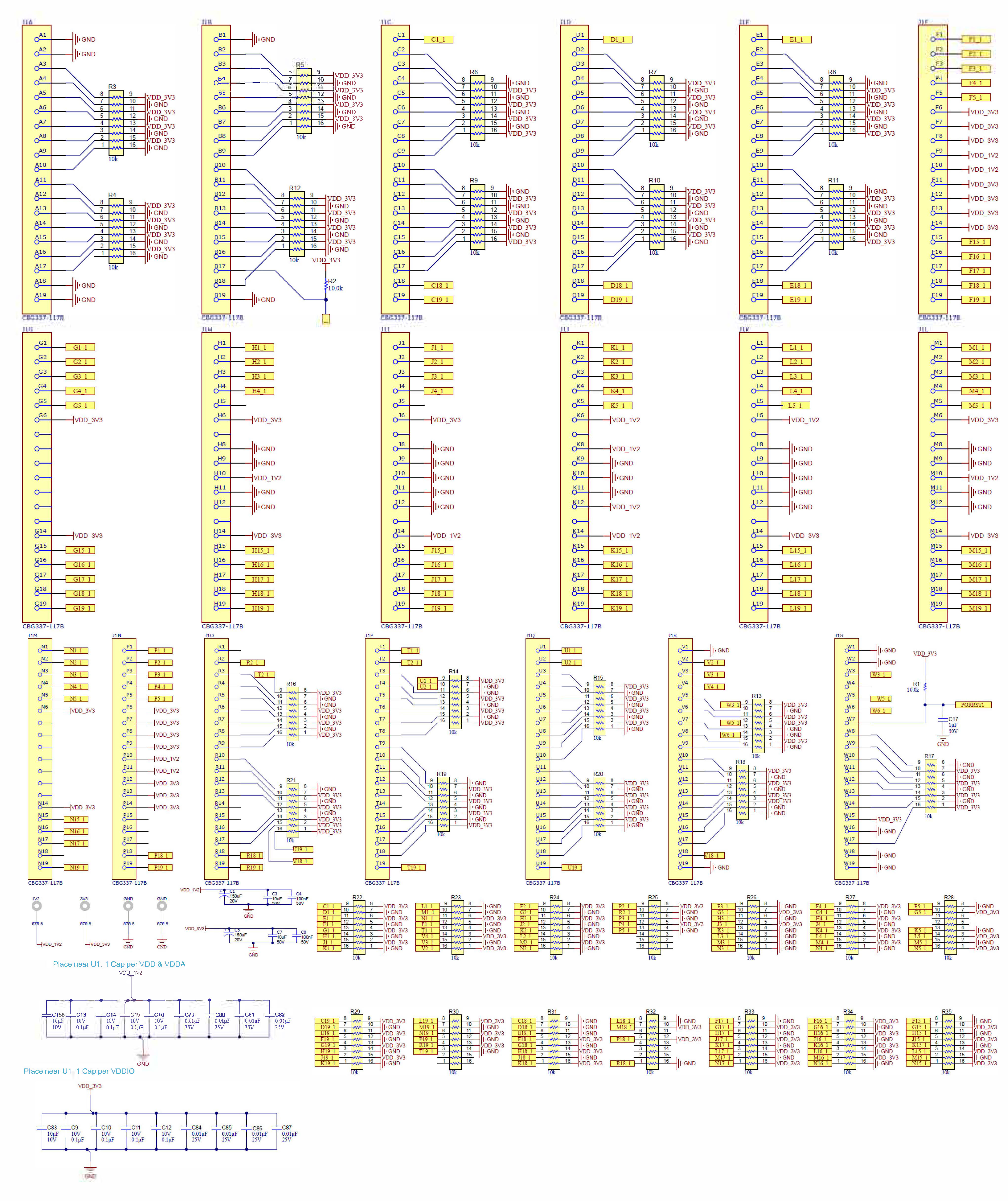
For the biased HDR conditions, the device was biased as shown below during HDR exposure with supply conditions as PS1 = 2.1V, PS2 = 4V, and PS3=4.2V.
 Figure 2-1 TMS570LC4357-SEP Bias Diagram
Test Configuration and Condition
A step-stress (for LDR: 20k and 30k, for HDR: 10k, 20k, 30k, 40k) test method was used to determine the TID hardness level. After a predetermined TID level was reached, an electrical test was performed on a given sample of parts to verify that the units are within specified data sheet electrical test limits. MIL-STD-883, Test Method 1019.9, Conditions A and B was used.
| LDR = 10 mrad(Si)/s; Aeroflex RAD, Colorado Springs, CO | |
|---|---|
| Total Samples: Six units, unbiased | |
| Exposure Levels (2) | |
| 20krad(Si) | 30krad(Si) |
| Unbiased | Unbiased |
| Units 1,2,3 | Units 4, 5, 6 |
| HDR = 65rad(Si) / s; Aeroflex RAD, Colorado Springs, CO. |
|---|
| Total Samples: Three units, biased |
| Exposure Levels (1) |
| 30krad(Si) |
| Biased |
| Units 7, 8, 9 |
| HDR = 188rad(Si)/s; Texas Instruments, Dallas, TX. |
|---|
| Total Samples: 20 units, biased |
| Exposure Levels (4) |
| 10krad(Si), 20krad(Si), 30krad(Si), 40krad(Si) |
| Biased |
| Five units at each dose level (units 10-29) |