SPRAA99C March 2008 – May 2021 AM3351 , AM3352 , AM3354 , AM3356 , AM3357 , AM3358 , AM3359 , AM4372 , AM4376 , AM4377 , AM4378 , AM4379 , OMAPL138B-EP , TMUX646
5.3 Tape Format
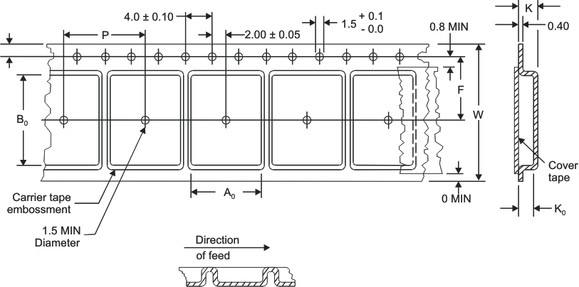
Typical tape format is shown in Figure 5-5. The variables used in Figure 5-3 and Table 5-1 are defined as follows: W is the tape width; P is the pocket pitch; and F is the distance between the drive hole and the centerline of the pocket.
 Figure 5-3 Single
Sprocket Tape Dimension
Figure 5-3 Single
Sprocket Tape Dimension| Tape Width (W) | Pocket Pitch (P) | Centerline to Drive Hole (F) | Package Size(1) |
|---|---|---|---|
| 16 | 8 | 7.5 | 6 × 6 |
| 16 | 12 | 7.5 | 8 × 8 |
| 24 | 16 | 11.5 | 10 × 10 |
| 24 | 16 | 11.5 | 12 × 12 |
| 24 | 16 | 11.50 | 13 × 13 |
| 24 | 24 | 11.50 | 14 × 14 |
| 8 | 4 | 3.5 | 2 × 1.4 |
| 8 | 4 | 3.5 | 2 × 2.5 |
| 12 | 4 | 5.5 | 2.45 × 2.45 |
| 12 | 4 | 5.5 | 2.5 × 3 |
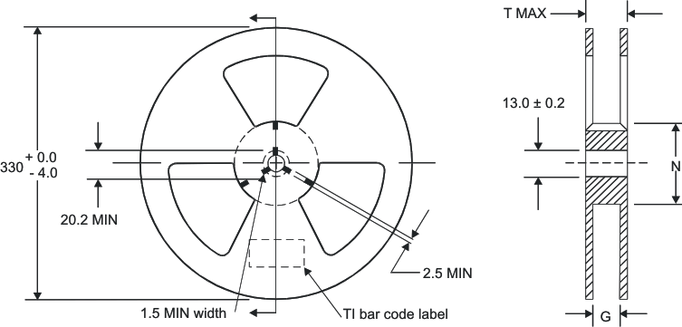
The reels are shown in Figure 5-4. In this figure, G is the width of the tape, N is the diameter of the hub, and T is the total reel thickness.
 Figure 5-4 Reel
Dimensions
Figure 5-4 Reel
Dimensions| Tape Width (G) | Parts per Reel |
|---|---|
| 16 | 2500 |
| 24 | 1000 |
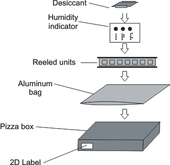
After the parts are loaded into the reel, each individual reel is packed in its own “pizza” box for shipping, as shown in Figure 5-5.
 Figure 5-5 Tape-and-Reel Packing