SPRAC03 July 2024 IWR6843
3.2 Detection Zone
IEC 61496-5:4.2.12.2
By definition of the standard in Section 4.1.3, when a target is within the detection zone, an Output Signal Switching Device (OSSD) must switch the Electro-Sensitive Protective Equipment (ESPE) to the OFF state. A single fault resulting in deterioration of ESPE detection must create a lock-out condition of at least 5 seconds. The IWR6843 used in these tests acts as both the OSSD and ESPE due to the chip performing both the sensing and switching.
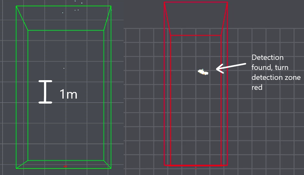
To emulate this, the Applications Visualizer (1) is used to visualize the detection zone’s size and status. When the zone is green, there is nothing being detected and no danger. When the zone is red, there is a detection and any electronics connected to the OSSD must be turned off to create a lock-out state. Note that all the processing and determination of zone size and status is done on the IWR6843 chip itself, with the visualizer only displaying the sensor point cloud output with no additional processing. Processing done on-chip includes the configured static clutter removal, where any detection with a Doppler of 0 is unreported. This prevents the detection of completely static objects such as walls and floors that clutter the point cloud.
In the visualizations of the radar output throughout this document, there is occasionally one or two single points of detection sporadically when there is no target or no movement. These are simple reflections, also known as noise or ghost points, and do not represent what the point cloud looks like when a real target is in view. These ghost points will importantly only cause over-detection, and not under-detection. Even with the 0.17 m2 CR that represents the 99th percentile of an adult human according to ISO 7250-1, the CR appears with over 20 detections clustered tightly together.
 Figure 3-3 Detection Zone Visualization
Example