SPRAC03 July 2024 IWR6843
4.6 Manual Interference
IEC 61496-5:5.4.8
For safety purposes, the sensor must be immune to coverings. In Section 5.4.8, the standard calls for a test where 50% of the transmitting antennas are covered by a sheet of aluminum foil, and for the sensor to know that there is something covering it.
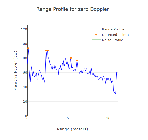
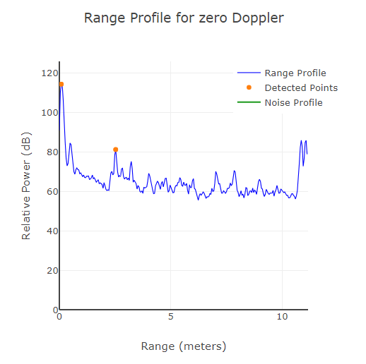
Due to the nature of the test, the point cloud is not the best visualization of the results due to points showing up in the 0th range bin due to antenna coupling. However, when looking at the range profile’s 0th range bin, there is always at least a 20 dB increase in power when the aluminum foil covering was placed. This shows a large delta between antenna coupling, and antenna coupling with a reflective covering.
Figure 4-8 shows that the range profile was done using the browser mmWave Demo Visualizer tool.
 No Covering
 With Covering
Due to the large delta of first few range bins seen between the setup with and without covering, monitoring these first few range bins and looking for any large jump in reflective power creates an effective solution to passing this test.